
Annuloplasty implant

a technology of annuloplasty and implants, which is applied in the field of annuloplasty implants, can solve the problems of valve leakage, material rupture, impede optimal functioning, etc., and achieve the effects of facilitating tailoring, less cost, and facilitating the manufacturing of annuloplasty implants

Active Publication Date: 2020-07-02
MEDTENTIA INT LTD OY
View PDF2 Cites 3 Cited by
  • Summary
  • Abstract
  • Description
  • Claims
  • Application Information

AI Technical Summary

Benefits of technology

The disclosure is about a way to make a heart valve repair device that is cheaper to produce. This can help make the procedure more affordable for patients who need it.

Problems solved by technology

The mitral and tricuspid valve leaflets or supporting chordae may degenerate and weaken or the annulus may dilate leading to valve leak.
A problem with prior art annuloplasty implants lack of flexibility of the implant in certain situations, which impedes optimal functioning when implanted in the moving heart, or adaptability to varying anatomies.
Material fatigue may nevertheless lead to rupture of the material, which may be unexpected and uncontrolled.
This entails a higher risk to the patient and it is thus a further problem of prior art devices.
A further problem with prior art annuloplasty implants is the complex manufacturing thereof.
Annuloplasty implants may have to be manufactured by time-consuming milling processes.
Such manufacturing processes may also impede patient specific tailoring of the implants.
The annuloplasty implants are thus cumbersome to optimize to the anatomy of the specific patient.
This entails a higher risk to the patient and is thus a further problem of prior art devices.
The above problems may have dire consequences for the patient and the health care system.
Patient risk is increased.

Method used


Image

  • Annuloplasty implant
  • Annuloplasty implant
  • Annuloplasty implant

Examples


Embodiment Construction

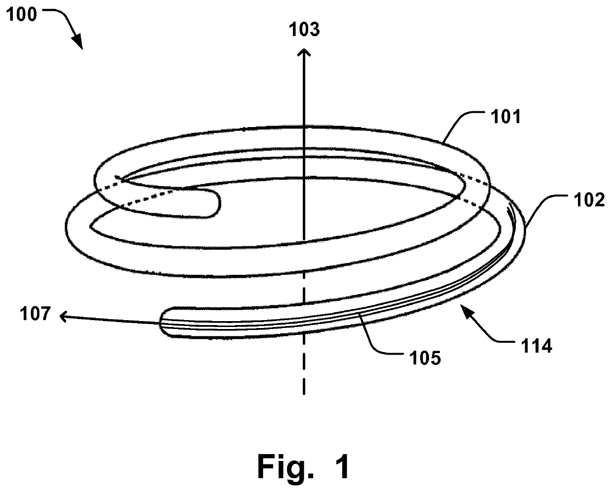
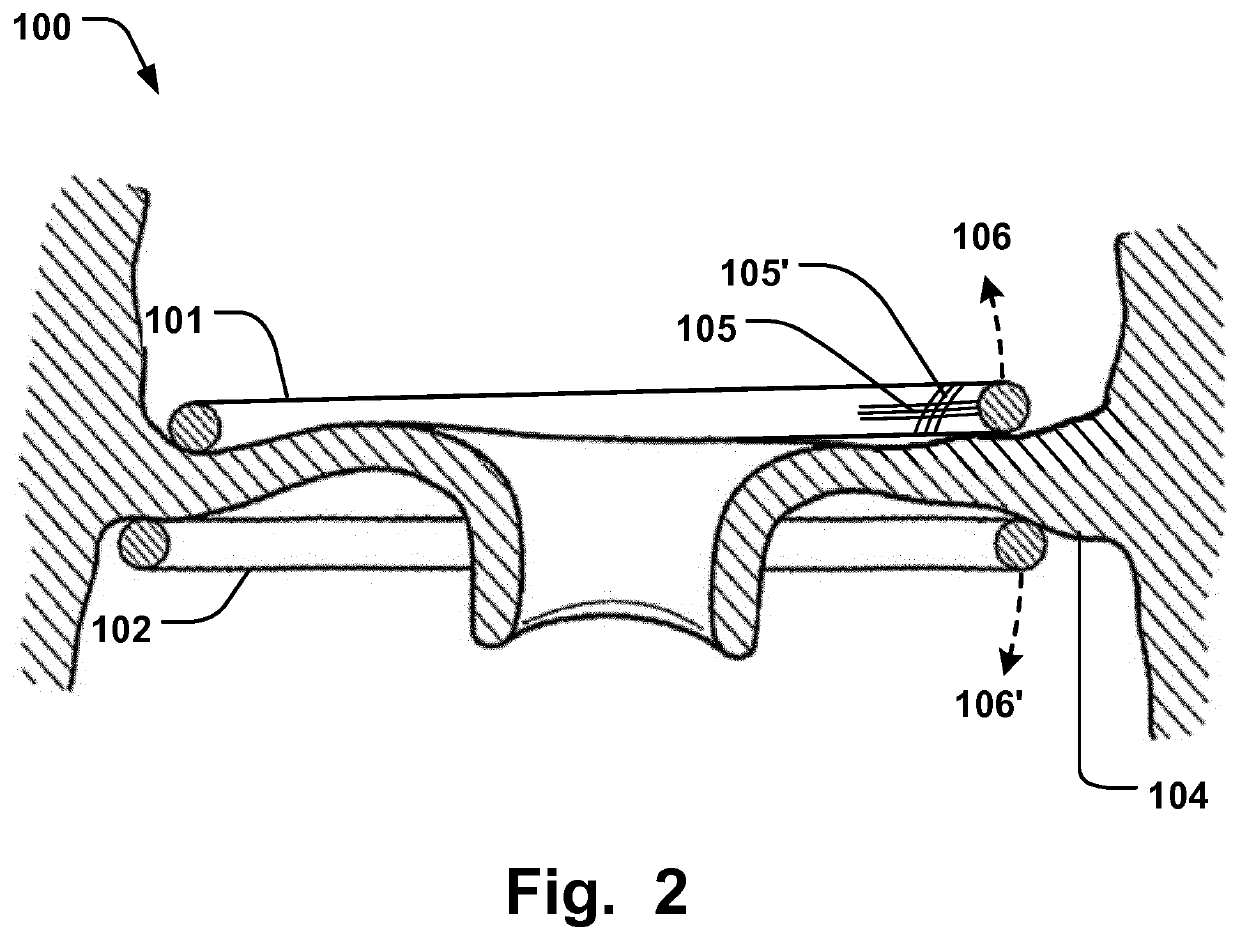
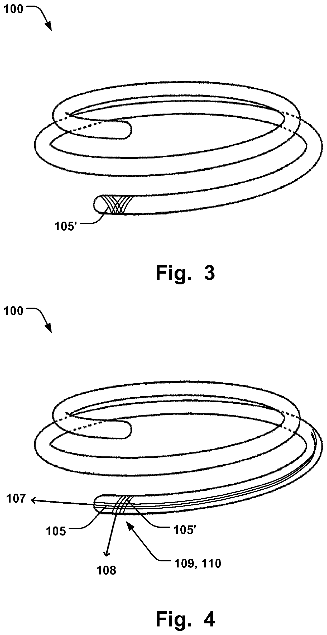
[0036]Specific embodiments of the invention will now be described with reference to the accompanying drawings. This invention may, however, be embodied in many different forms and should not be construed as limited to the embodiments set forth herein; rather, these embodiments are provided so that this disclosure will be thorough and complete, and will fully convey the scope of the invention to those skilled in the art. The terminology used in the detailed description of the embodiments illustrated in the accompanying drawings is not intended to be limiting of the invention. In the drawings, like numbers refer to like elements.

[0037]The following description focuses on an embodiment of the present invention applicable to cardiac valve implants such as annuloplasty rings. However, it will be appreciated that the invention is not limited to this application but may be applied to many other annuloplasty implants and cardiac valve implants including for example replacement valves, and o...


PUM


Abstract

An annuloplasty implant (100) is disclosed comprising first and second support rings (101, 102) arranged in a coiled configuration around an axial direction (103), and being adapted to be arranged on opposite sides of native heart valve leaflets to pinch said leaflets. At least part of said first and second support ring is formed from a carbon fiber material (105). The first and second support rings are resiliently movable with respect to each other in opposite directions along said axial direction. A method of manufacturing an annuloplasty implant is also disclosed.

Description

FIELD OF THE INVENTION[0001]This invention pertains in general to the field of cardiac valve replacement and repair. More particularly the invention relates to an annuloplasty implant, such as an annuloplasty ring or helix, for positioning at the heart valve annulus and a method of manufacturing an annuloplasty implant.BACKGROUND OF THE INVENTION[0002]Diseased mitral and tricuspid valves frequently need replacement or repair. The mitral and tricuspid valve leaflets or supporting chordae may degenerate and weaken or the annulus may dilate leading to valve leak. Mitral and tricuspid valve replacement and repair are frequently performed with aid of an annuloplasty ring, used to reduce the diameter of the annulus, or modify the geometry of the annulus in any other way, or aid as a generally supporting structure during the valve replacement or repair procedure.[0003]A problem with prior art annuloplasty implants lack of flexibility of the implant in certain situations, which impedes opti...

Claims


Application Information

Patent Timeline
Patent Type & Authority Applications(United States)
IPC IPC(8): A61F2/24
CPCA61F2/2463A61F2240/002A61F2/2445A61F2230/0091
Inventor ZERKOWSKI, HANS-REINHARDKERÄNEN, OLLI
Owner MEDTENTIA INT LTD OY
Learn More