Depth correction in pixellated detectors of ionizing radiation

a detector and depth correction technology, applied in the direction of radiation measurement, instruments, measurement devices, etc., can solve the problems of limiting the overall rate of interaction events, difficult to distinguish in the cathode signal, and the over-inverse dependence of cce on interaction depth

Active Publication Date: 2020-07-02
UK RES & INNOVATION LTD
View PDF0 Cites 4 Cited by
  • Summary
  • Abstract
  • Description
  • Claims
  • Application Information

AI Technical Summary

Benefits of technology

[0019]Positive features in one or more first pixels may be determined to be for the same interaction event as negative features in adjacent or nearby pixels by virtue of these features being from the same or corresponding detection or readout periods. However, since multiple positive and / or negative features may sometimes be detected in a single detection period in a single pixel or adjacent pixels, the detector may further comprise one or more time stamp circuits arranged to output a time stamp of any detected and output positive or negative feature(s) in a particular detection period, so that it can be better determined in such positive and negative features do indeed correspond to the same interaction event.

Problems solved by technology

However, for radiation energies with average penetration depths within the semiconductor layer which are comparable to or greater than the thickness of the layer, the above inverse dependence of CCE on interaction depth is a significant technical problem for the design and operation of such detectors.
He et al. use a single, large planar cathode, so if two interaction events occur close together in time at the detector, they will be difficult to distinguish in the cathode signal, even if the event gives rise to signals in different pixel anodes, limiting the overall rate of interaction events, and therefore which can be detected with spectral detail.
Dividing the cathode into multiple separate sub-cathodes can partly address this problem, but then makes instrumentation of the electrodes more complex, and weakening the relationship between cathode and anode signals being relied upon for depth of interaction determination.

Method used


Image

  • Depth correction in pixellated detectors of ionizing radiation
  • Depth correction in pixellated detectors of ionizing radiation
  • Depth correction in pixellated detectors of ionizing radiation

Examples


Embodiment Construction

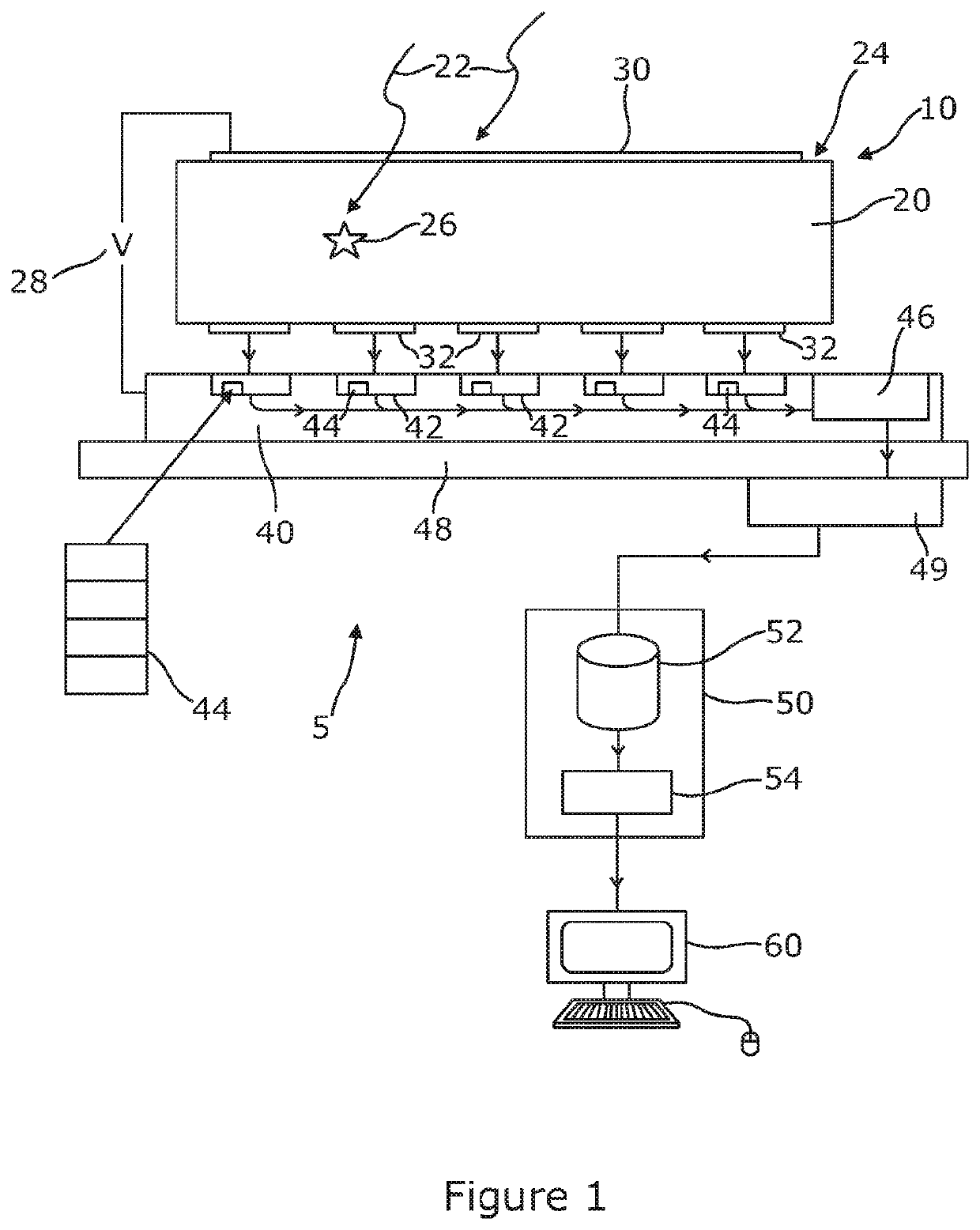
[0053]Referring now to FIG. 1, a schematic view is shown of a spectroscopic imaging sensor 5 for detecting particles or photons of ionizing radiation 22, such as Gamma rays or X-rays, and in particular such sensor which can output information about spectral properties of that radiation with lateral position information, for example in the form of a pixelated image. Typical uses for a spectroscopic imaging sensor of ionizing radiation such as that of FIG. 1 are situations where spectroscopic X-ray imaging is required, for example in medical, security, astronomy, and industrial imaging areas.

[0054]The sensor 5 includes a detector portion 10 and an application specific integrated circuit 40 (ASIC) arranged to process electrical signals from the detector 10. The detector comprises a semiconductor layer 20 into which ionizing radiation 22 to be detected enters at a front face 24 of the layer 20. At least some of the ionizing radiation interacts with the material of the semiconductor laye...


PUM


Abstract

The disclosure relates to spectroscopic sensors of ionizing radiation, and the use of an application specific integrated circuit to detect both positive features in a pixel anode signal indicative of ionizing radiation interacting with that pixel, and negative features indicative of ionizing radiation interacting in an adjacent or proximal pixel. For this purpose, both positive and negative peak hold circuits may be provided in each ASIC pixel circuit.

Description

[0001]The present invention relates to direct conversion semiconductor detectors of ionizing radiation, and in particular such sensors having pixelated arrays of electrodes so as to detect position of a radiation interaction event with the sensor.[0002]By way of example only, the invention may be used in the field of X-ray or Gamma ray imaging spectroscopy, and the detector may be implemented using a monolithic layer of a semiconductor such as Cd(Zn)Te or GaAs on which a pixelated array of anodes is provided at a rear face of the semiconductor layer. The detector may in particular be a small pixel detector, for example in which the pixel pitch is less than half of the thickness of the semiconductor layer.INTRODUCTION[0003]Direct conversion spectral detection of ionizing radiation can be carried out using a layer of semiconductor material to capture incident radiation so as to generate positive and negative charge, typically electrons and holes, within the material. A bias voltage im...

Claims


Application Information

Patent Timeline
Patent Type & Authority Applications(United States)
IPC IPC(8): G01T1/24
CPCG01T1/241G01T1/247
Inventor VEALE, MATTHEW
Owner UK RES & INNOVATION LTD
Why Eureka
Try Eureka