
Automatic sand abrasion device

a sand abrasion and automatic technology, applied in the direction of instruments, manufacturing tools, material analysis, etc., can solve the problems of high manpower and material resources, low detection capacity and accuracy, and low efficiency, so as to improve the detection efficiency of sand abrasion resistance, reduce labor costs, and improve the effect of accuracy and efficiency

Pending Publication Date: 2020-07-16
CITIC DICASTAL
View PDF6 Cites 3 Cited by
  • Summary
  • Abstract
  • Description
  • Claims
  • Application Information

AI Technical Summary

Benefits of technology

The present disclosure provides an automatic sand abrasion device that can improve the detection efficiency for the abrasion resistance of a paint, reduce labor cost, and improve the accuracy and efficiency of experiment. The device uses a transport belt and second speed reduction motor for transporting sand, and an automatic weighing machine for weighing sand. The device is designed to prevent the transport belt from falling off and to discharge tiny dust produced during the operation process. The device also includes a sand baffle plate and ringlike sand speed reduction chamfering ditch to improve the accuracy of the experiment. The transport belt locating slot and transport belt locating rod, as well as the side wall of the shell with the transport belt tightening device, make the device firm in structure and stable and reliable in work. Overall, the device improves the detection efficiency for abrasion resistance, reduces labor cost, and enhances the accuracy and efficiency of experiment.

Problems solved by technology

This measure not only consumes a lot of manpower and material resources, but also has a great impact on human health since tiny dust may suffuse in air during the impacting.
In addition, such measure is relatively low in detection capacity and accuracy and is very low in efficiency.

Method used


Image

  • Automatic sand abrasion device
  • Automatic sand abrasion device
  • Automatic sand abrasion device

Examples


Embodiment Construction

[0030]Referring to FIGS. 1 to 7, one embodiment provided by the present disclosure is as follows.

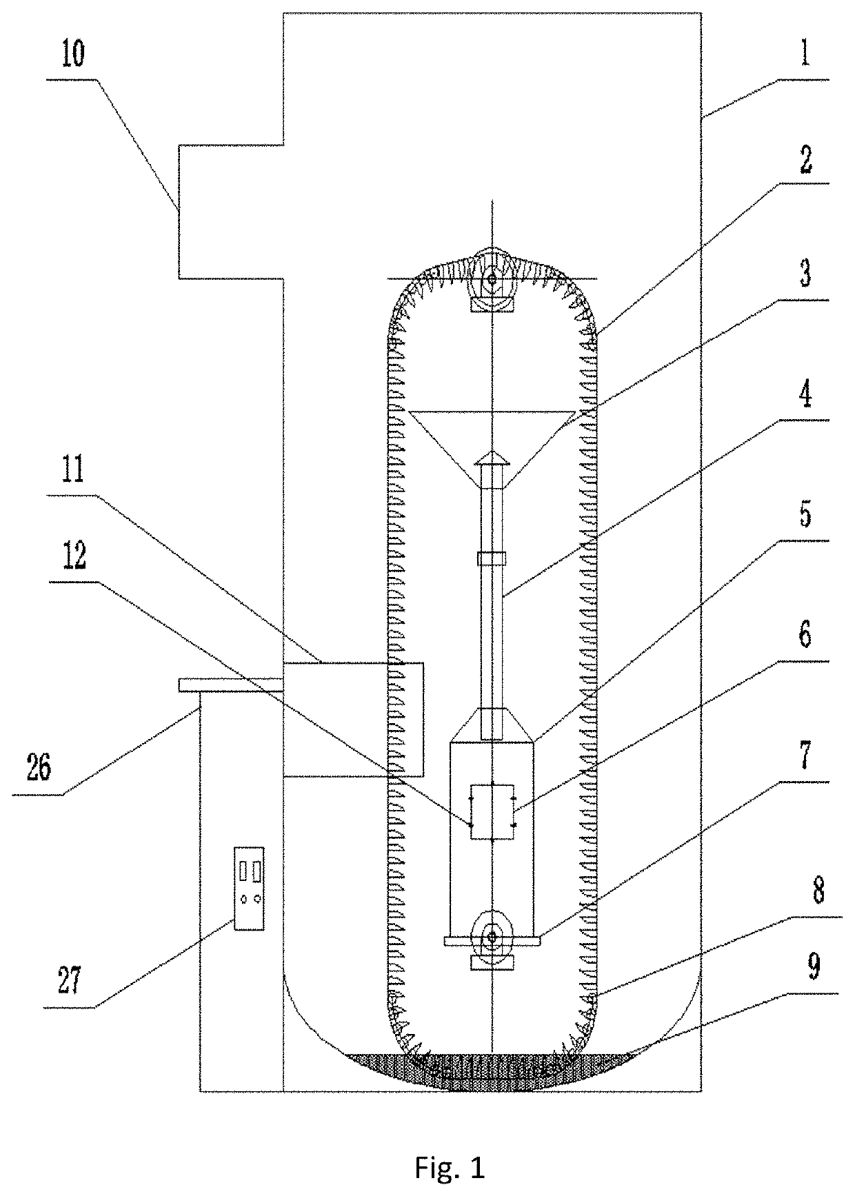
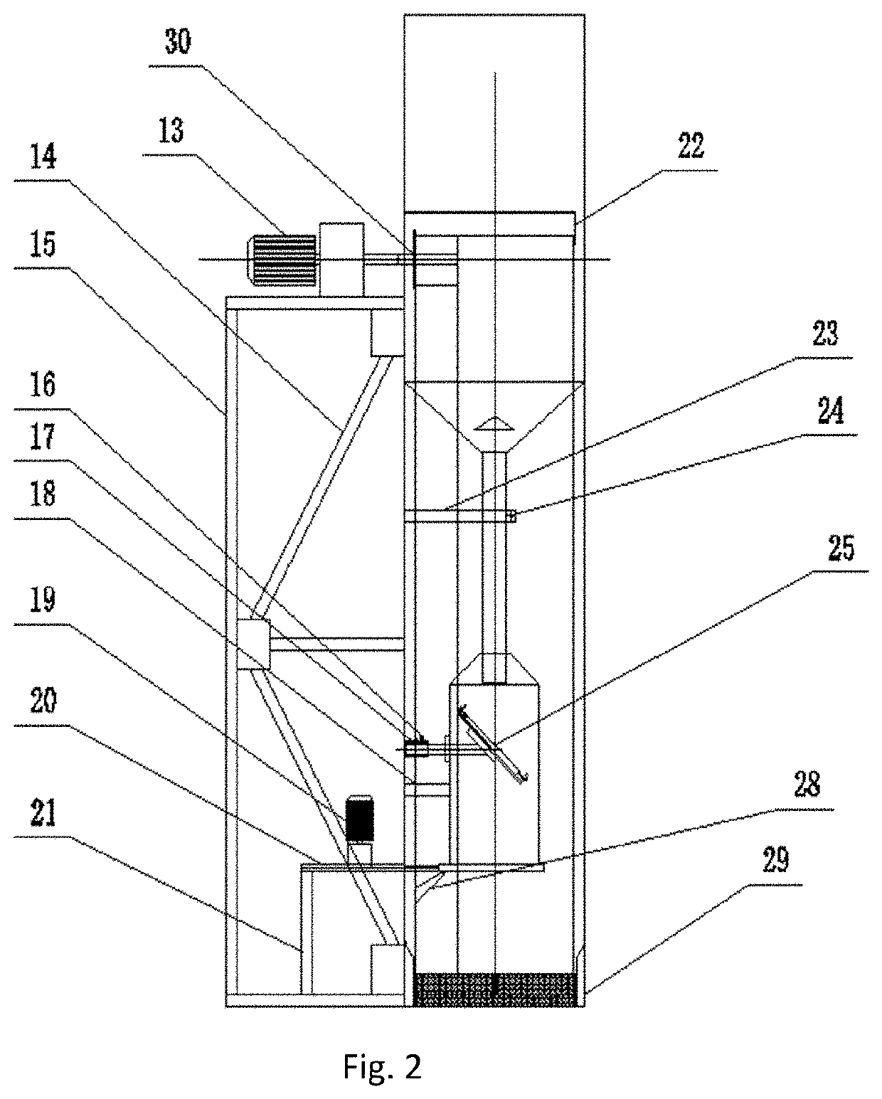
[0031]An automatic sand abrasion device is characterized by including a shell 1, an integrated framework, a sand falling mechanism, a sand transport mechanism, a sand falling channel, a sample working frame and a circuit control cabinet 26. The integrated framework includes an experiment table supporting frame 15, supporting rods 14 and a weighing machine bracket 21. The weighing machine bracket 21 is fixedly mounted at the bottom in the experiment table supporting frame 15. The supporting rods 14 are fixedly disposed in the experiment table supporting frame 15 to allow the integrated framework to be firmer. In the present embodiment, the supporting rods and the weighing machine bracket are welded inside the experiment table supporting frame. The shell 1 is welded on the experiment table supporting frame 15, and the integrated framework, the sand falling mechanism, the sand transport mec...


PUM


Abstract

An automatic sand abrasion device includes a shell, an integrated framework, a sand falling mechanism, a sand transport mechanism, a sand falling channel, a sample working frame and a circuit control cabinet, where the device adopts the transport belt and the second speed reduction motor to realize transportation of sand, and realizes that the weighed sand falls into the bottom of the abrasion device through the first speed reduction motor and the automatic weighing machine. The whole process can be automatically operated while parameters such as the operation time and the weight of abrasion sand are set, so that the detection efficiency for the abrasion resistance can be improved, and the labor cost is greatly reduced. The device is firm in structure and stable and reliable in work and improves the accuracy and efficiency of an experiment.

Description

CROSS REFERENCE TO RELATED APPLICATION[0001]This application claims priority to Chinese Patent Application No. 201910034694.3, entitled AUTOMATIC SAND ABRASION DEVICE and filed on Jan. 15, 2019, which is incorporated herein by reference for all purposes.FIELD OF THE INVENTION[0002]The present disclosure relates to the technical field of verification of sand abrasion resistance of coated surface paints, and more particularly relates to an automatic sand abrasion device.BACKGROUND OF THE INVENTION[0003]With the upgrading of automobile consumption, people pay more and more attention to the appearance of automobiles, and the more beautiful the appearance of an automobile is, the more popular the automobile is. The quality of a paint is directly related to whether the appearance of the automobile is accepted by the public. Therefore, automobile manufacturers pay special attention to the various properties of the paint. The abrasion resistance of the paint is directly related to whether t...

Claims


Application Information

Patent Timeline
IPC IPC(8): B24C3/02
CPCB24C3/02G01N3/56G01N2203/0032B24C7/0092
Inventor ZHOU, JIWEIMA, CHAOZHENG, LIQUNYUAN, HAIFENG
Owner CITIC DICASTAL
Learn More