
Circuit carrier for a battery system and battery system

Active Publication Date: 2020-07-23
SAMSUNG SDI CO LTD
View PDF1 Cites 0 Cited by
  • Summary
  • Abstract
  • Description
  • Claims
  • Application Information

AI Technical Summary

Benefits of technology

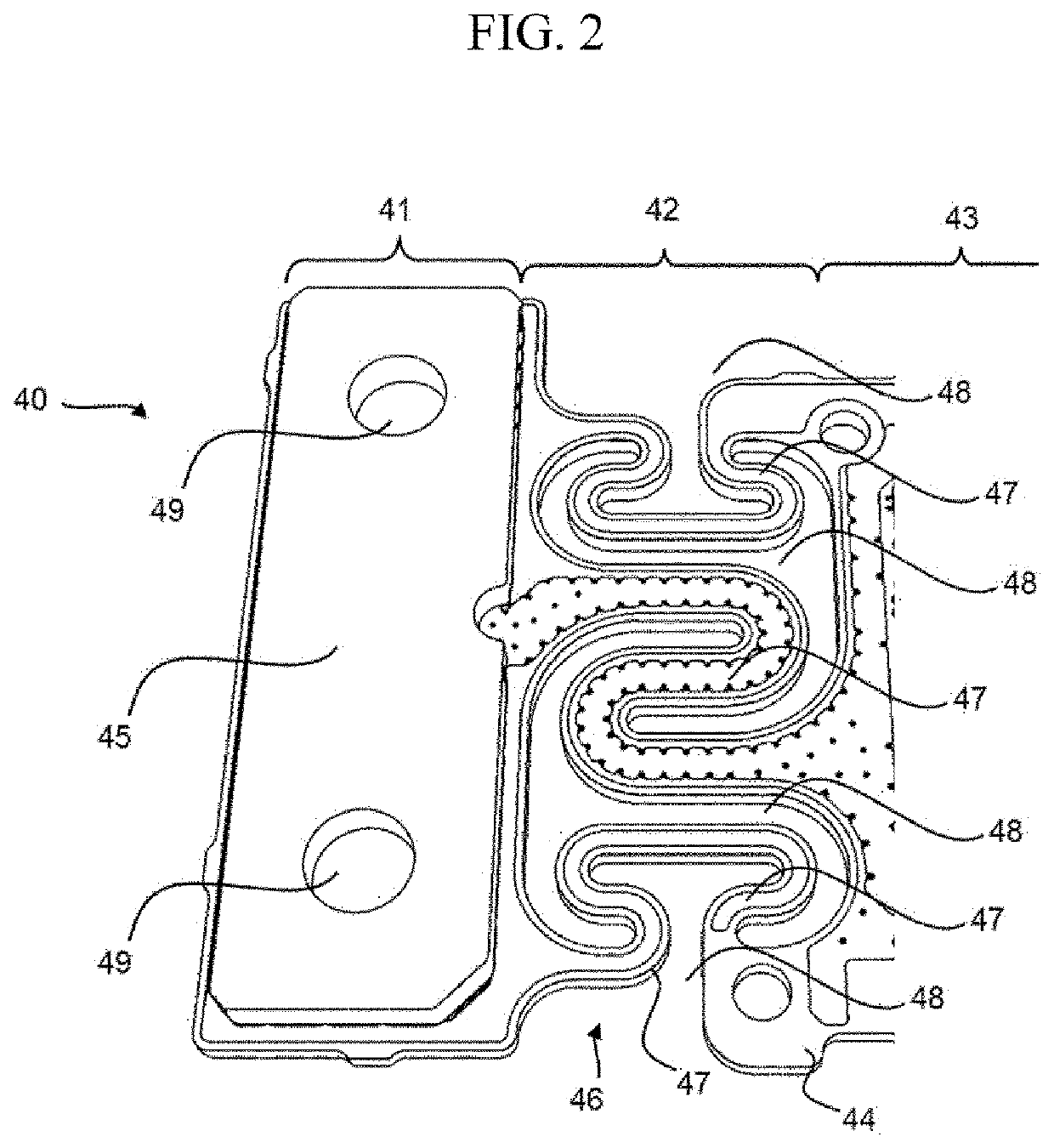
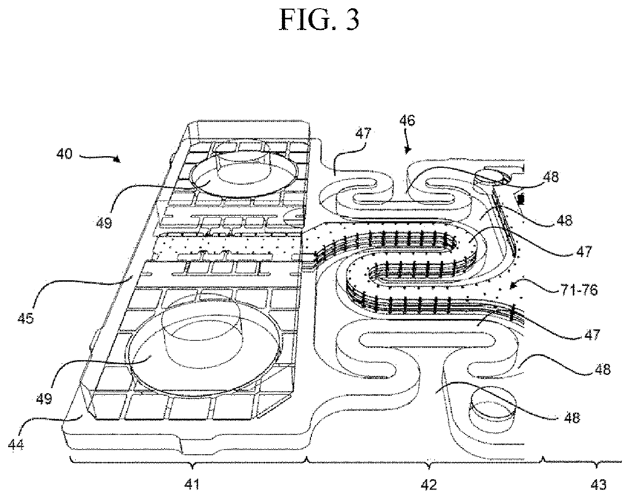
The present invention provides a circuit carrier for a battery system control unit that reduces mechanical stress on sensitive components mounted thereon. The circuit carrier allows for mechanical decoupling of different regions, reducing transmission of mechanical impacts and vibrations. The circuit carrier also allows for compensation of dimensional changes without stressing the components installed on it. The circuit carrier includes a spring-like structure and a meandering-shaped structure formed by milling or other suitable material removing techniques. The at least one voltage path is enclosed by electrical shielding to improve shunt current measurement and ensure accurate voltage measurement.

Problems solved by technology

If the heat emission / discharge / dissipation is not sufficiently performed, temperature deviations occur between respective battery cells, such that the battery module may no longer generate an anticipated amount of power.
In addition, an increase in the internal temperature of a rechargeable battery can lead to abnormal reactions occurring therein, and thus, charging and discharging performance of the rechargeable battery may deteriorate and the life-span of the rechargeable battery may be shortened.
Static control of the battery power output and charging may not be sufficient to meet the dynamic power demands of various electrical consumers connected to the battery system.
These connections between the PCB and the housing and the shunt and the bus bar may transfer mechanical stress, such as by bending or flexing, to the PCB, particularly because the PCB is often mechanically weaker than the connected housing and bus bars.
Additionally, mechanical stress may arise during operation of the PCB when dimensional changes of the battery cells and / or the housing, for example, due to temperature changes, cell swelling, aging, etc., differ from dimensional changes of the PCB.
These components can also be damaged by the application of mechanical stress to the PCB.
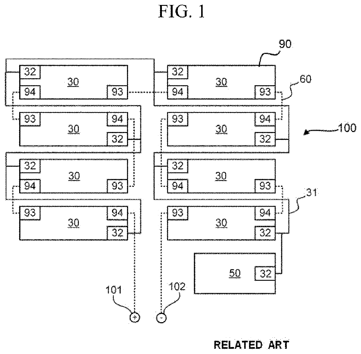
However, if the battery system includes a plurality of battery modules, each with a CSC as described above, the BMS circuit carrier may not be directly connected to a battery module.
However, additional voltage paths are required to provide redundant signals to the voltage measurement circuit.
Electrical shielding improves the shunt current measurement, as the voltage levels measured across the shunt may be as low as a about few microvolts and electromagnetic interference levels present in the automotive environment may, thus, greatly decrease the measurement accuracy.

Method used


Image

  • Circuit carrier for a battery system and battery system
  • Circuit carrier for a battery system and battery system
  • Circuit carrier for a battery system and battery system

Examples


Embodiment Construction

[0046]Reference will now be made in detail to embodiments, examples of which are illustrated in the accompanying drawings. Aspects and features of the present invention, and implementation methods thereof, will be described with reference to the accompanying drawings. In the drawings, like reference numerals denote like elements, and redundant descriptions thereof may be omitted. The present invention, however, may be embodied in various different forms and should not be construed as being limited to the embodiments illustrated herein. Rather, these embodiments are provided as examples so that this disclosure will be thorough and complete and will fully convey the aspects and features of the present invention to those skilled in the art. Accordingly, processes and elements considered not necessary for those having ordinary skill in the art to have a complete understanding of the aspects and features of the present invention may not be described in detail. In the drawings, the relati...


PUM


Abstract

A circuit carrier is configured to be mounted to a battery system. The circuit carrier includes a circuit carrier board having a first region, a second region, and a third region. The first region is configured to receive a shunt resistor, the third region is configured to receive further electronic components, and the first region and the third region being separated from each other by the second region. The second region is a flexible connection between the first region and the third region and includes a spring-like structure formed from the circuit carrier board.

Description

CROSS-REFERENCE TO RELATED APPLICATION[0001]This application claims priority to and the benefit of Korean Patent Application No. 10-2020-0006085, filed in the Korean Intellectual Property Office on Jan. 16, 2020, and European Patent Application No. 19152476.8, filed in the European Patent Office on Jan. 18, 2019, the entire contents of which are incorporated herein by reference.BACKGROUND1. Field[0002]Aspects of embodiments of the present invention relate to a circuit carrier for a battery system and a battery system including such a circuit carrier.2. Related Art[0003]A rechargeable (or secondary) battery differs from a primary battery in that it is designed to be repeatedly charged and discharged, while the latter is designed to provide an irreversible conversion of chemical to electrical energy. Low-capacity rechargeable batteries may be used as a power supply for small electronic devices, such as cellular phones, notebook computers, and camcorders, while high-capacity rechargeab...

Claims


Application Information

Patent Timeline
IPC IPC(8): H05K1/02H05K1/18G01R19/00H01M10/42H05K1/11H01M10/48
CPCH05K2201/10022H01M10/425H05K2201/10037H01M2010/4271H05K1/115H01M10/48H05K1/189H05K2201/10151G01R19/0084H05K1/0278H05K2201/09263H05K2201/10272Y02E60/10
Inventor KURCIK, PETERKORHERR, THOMASWEISSENSTEINER, BIRGIT
Owner SAMSUNG SDI CO LTD
Learn More