
Contact lens and accessory

Active Publication Date: 2020-07-30
SONY CORP +1
View PDF4 Cites 0 Cited by
  • Summary
  • Abstract
  • Description
  • Claims
  • Application Information

AI Technical Summary

Benefits of technology

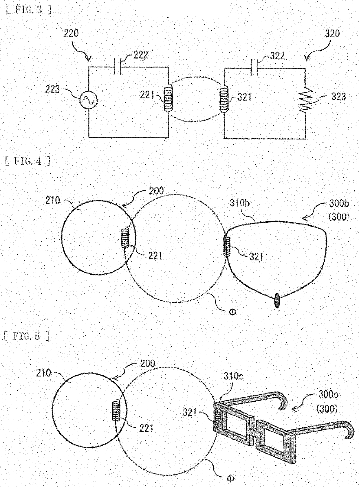
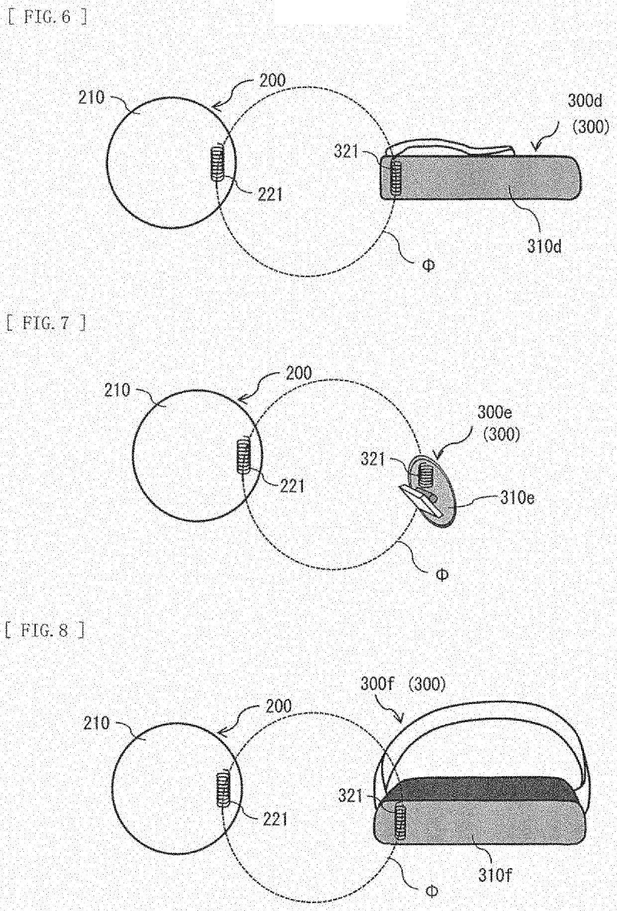
The present patent allows for a contact lens that can communicate wirelessly with an external device using magnetic coupling. The lens has coil antennas that extend in different directions, reducing the output level and allowing for a more efficient wireless communication. The capacitor is coupled to the coil antennas in series or parallel, further reducing the output level and power consumption. This technology allows for data transmission while minimizing the impact on the human body. The first and second accessories described in the patent have similar effects and can also be used with the contact lens.

Problems solved by technology

In a case where the contact lens is worn on an eyeball, the contact lens gets wet with tears, which makes it non-straightforward to carry data sent out from the contact lens a long way.
It is also considered to increase an output level of the data; however, such a case raises an issue with power consumption and an influence on a human body.

Method used


Image

  • Contact lens and accessory
  • Contact lens and accessory
  • Contact lens and accessory

Examples


embodiment

1. Embodiment

[Configuration]

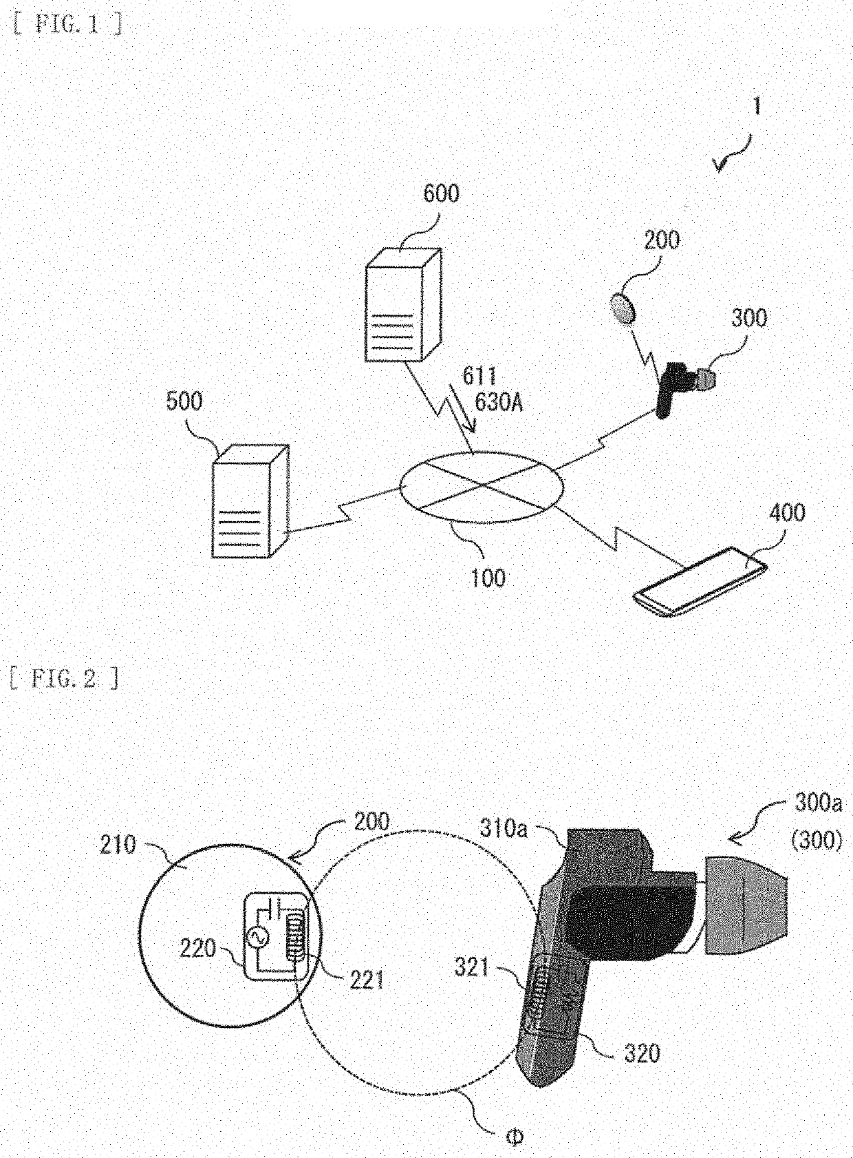
[0078]Description is provided on a biological information management system 1 according to an embodiment of the present disclosure. FIG. 1 illustrates a schematic configuration example of the biological information management system 1. The biological information management system 1 is a system that performs analysis in accordance with a request of a user on the basis of biological information of the user and outputs a result of the analysis to a mobile terminal (an external apparatus) owned by the user and the like.

[0079]The biological information management system 1 includes a contact lens 200, an accessory 300, a terminal unit 400, a data server unit 500, and a web server unit 600. The accessory 300, the terminal unit 400, the data server unit 500, and the web server unit 600 are coupled to one another over a network 100. The network 100 is, for example, a communication network that establishes communication using a communication protocol (TCP / IP) that ...

modification examples

2. Modification Examples

[0128]Next, description is provided on modification examples of the contact lens 200 and the accessory 300 according to the above-described embodiment.

modification example a

[0129]FIG. 24(A) illustrates an example of a planar configuration of a contact lens 200 according to a modification example A. FIG. 24(B) illustrates an example of a lateral configuration of the contact lens 200 according to the modification example A. In the present modification example, the coil section 221 takes a substantially circular form extending along an end edge of the lens section 210. In the coil section 221, an opening at one end and an opening at another end are directed in opposite directions.

[0130]Further, in the coil section 221, the opening at the one end and the opening at the other end are provided inside layers that are different from each other. Even in a case where the coil section 221 adopts such a configuration, it is possible to reduce the output level, and to achieve the wireless communication utilizing the magnetic coupling. As a result, it is possible to transmit data while suppressing the power consumption and the influence on a human body.


PUM


Abstract

A contact lens according to an embodiment of the present disclosure includes: a lens section that is worn on an eyeball; an acquisition section that is provided in the lens section and acquires biological information; and an output section that outputs the biological information acquired by the acquisition section to an external apparatus to be worn on a human body. The output section has one or a plurality of coil antennas extending along a front surface of the lens section, and a capacitor that is coupled to the one or the plurality of coil antennas in series or in parallel.

Description

TECHNICAL FIELD[0001]The present disclosure relates to a contact lens and an accessory.BACKGROUND ART[0002]In recent years, a method has been developed that acquires biological information using a contact lens.CITATION LISTPatent Literature[0003]PTL 1: WO2014 / 181568SUMMARY OF THE INVENTION[0004]Incidentally, in a case where data is transmitted from a contact lens to peripheral equipment, wireless communication is typically utilized. In a case where the contact lens is worn on an eyeball, the contact lens gets wet with tears, which makes it non-straightforward to carry data sent out from the contact lens a long way. It is also considered to increase an output level of the data; however, such a case raises an issue with power consumption and an influence on a human body. Therefore, it is desirable to provide a contact lens and an accessory that allow for data transmission while suppressing the power consumption and the influence on a human body.[0005]A contact lens according to an emb...

Claims


Application Information

Patent Timeline
IPC IPC(8): A61B5/00G02C7/04G02C11/00H01Q1/27H01Q7/00
CPCG02C7/04H04B5/02A61B3/113G02C11/10A61B5/14507A61B5/02007A61B5/6821H01Q7/00A61B3/16A61B5/1103A61B5/02438H01Q1/273A61B5/002H01Q1/44H01Q21/20H04B1/59A61B3/10A61B3/125A61B5/6824A61B5/6826A61B5/6828A61B5/6803A61B5/6895H04B5/72H04B5/26A61B3/101A61B5/0015H01Q7/06H04B5/48
Inventor IWASAKI, MASANORIHIRABAYASHI, TAKAYUKIYAMAGUCHI, NAOTOYOSHIMURA, TSUKASAYAJIMA, MASAKAZUSHIGA, FUMIKOHAYAKAWA, KEN
Owner SONY CORP
Learn More