Numerical control system
a control system and numerical control technology, applied in the field of numerical control systems, can solve problems such as the difficulty of creating a general-purpose machine learning device, and achieve the effect of efficient process
- Summary
- Abstract
- Description
- Claims
- Application Information
AI Technical Summary
Benefits of technology
Problems solved by technology
Method used
Image
Examples
first embodiment
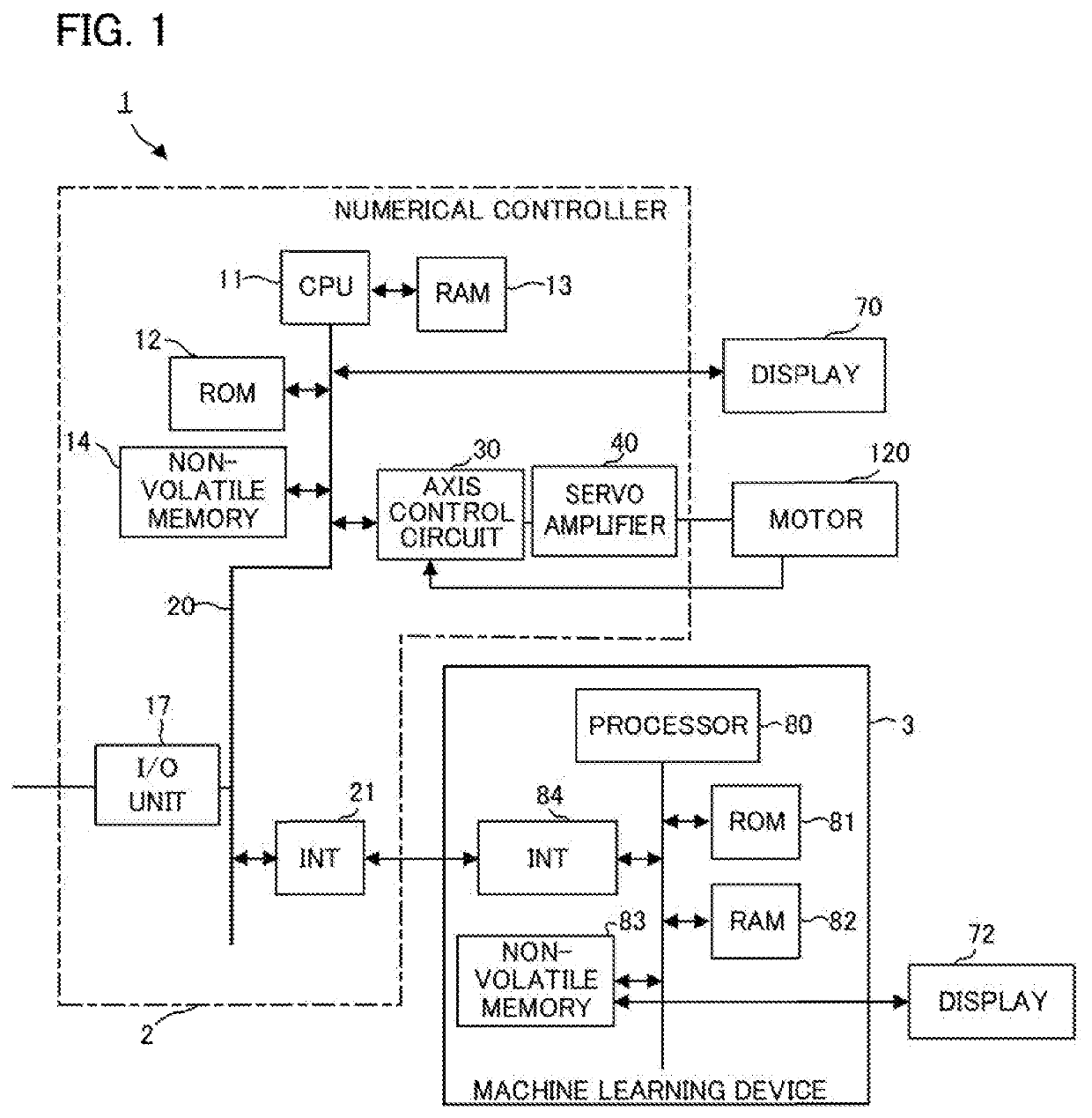
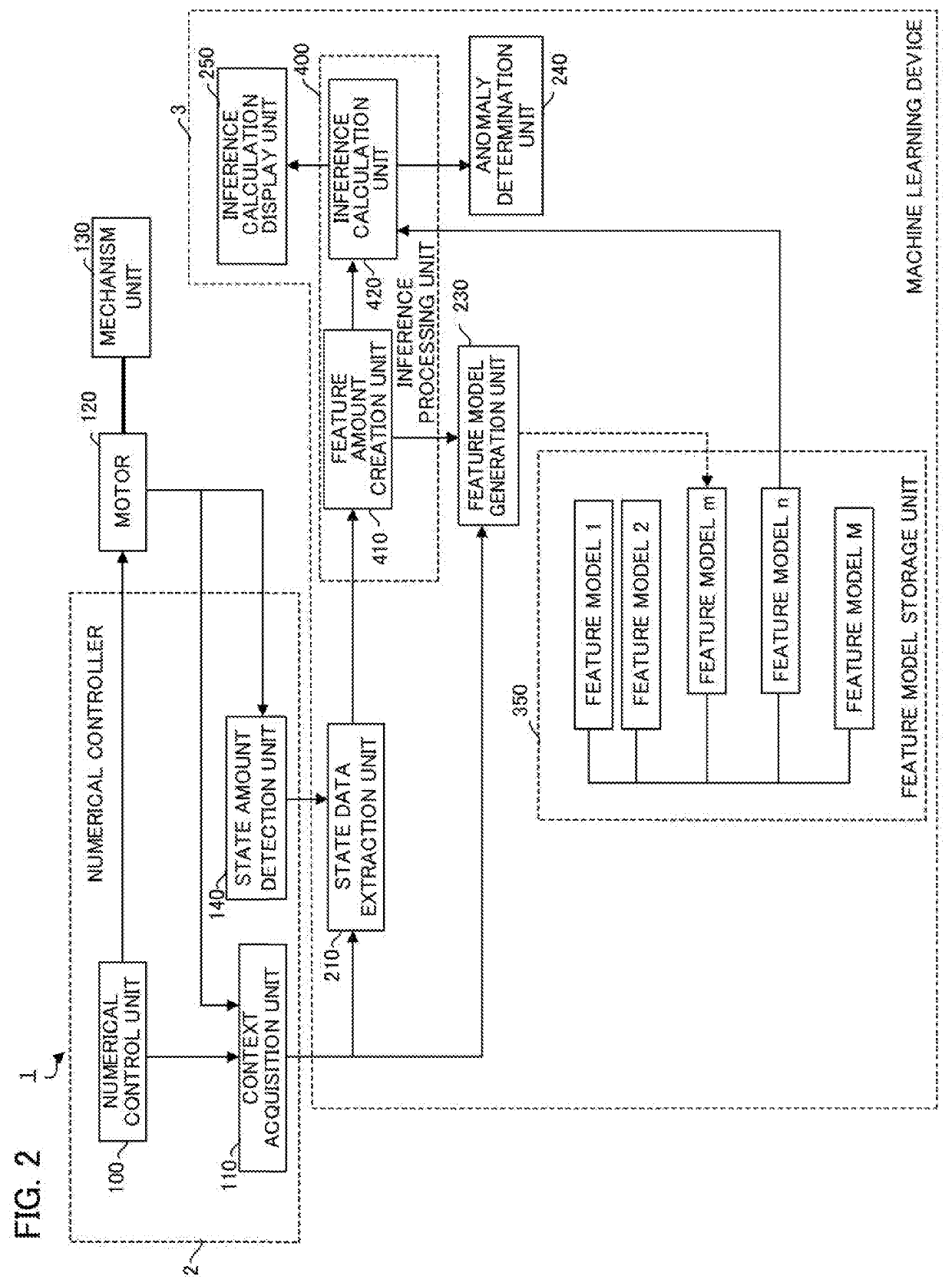
[0027]FIG. 2 is a schematic function block diagram of the numerical control system 1 according to the Each functional block illustrated in FIG. 2 is realized when the CPU 11 provided in the numerical controller 2 forming the numerical control system 1 illustrated in FIG. 1 or the processor 80 such as a GPU provided in the machine learning device 3 configured on a computer such as a fog computer, a cloud server, or the like controls the operation of respective components of the devices in accordance with respective system programs.
[0028]The numerical control system 1 of the present embodiment includes a numerical control unit 100, a context acquisition unit 110, and a state amount detection unit 140 on the numerical controller 2 as an edge device targeted for observation and inference of at least the state thereof. Further, the numerical control system 1 includes an inference machining unit 400 that performs inference on the state of an edge device and a feature model storage unit 3...
second embodiment
[0056]FIG. 5 is a schematic function block diagram of the numerical control system 1 according to a Each functional block illustrated in FIG. 5 is realized when the CPU 11 provided in the numerical controller 2 forming the numerical control system 1 illustrated in FIG. 1 or a processor 80 such as a GPU provided in the machine learning device 3 configured on a computer such as a fog computer, a cloud server, or the like controls the operation of respective components of the devices in accordance with respective system programs.
[0057]The numerical control system 1 of the present embodiment includes an extraction pattern storage unit 300 that stores and manages a plurality of extraction patterns and an extraction pattern generation unit 220 that creates and updates the extraction pattern stored in the extraction pattern storage unit 300 in addition to the configuration provided in the numerical control system of the first embodiment.
[0058]The extraction pattern storage unit 300 of the...
third embodiment
[0066]FIG. 6 is a schematic block diagram of the numerical control system 1 according to a In the numerical control system 1 of the present embodiment, all the function blocks are implemented in a single component of the numerical controller 2. With such a configuration, for example, the numerical control system 1 of the present embodiment can extract state data by using a suitable extraction pattern in accordance with a context in a machining operation such as an operation pattern of the motor 120 in a machining operation with a machine tool controlled by the numerical controller 2, a type of a tool used for machining, or a material of a work and determine the operation state of the machine tool using a suitable feature model. Further, respective extraction patterns or learning models can be generated / updated in accordance with a context in a machining operation by using a single numerical controller 2.
PUM
 Abstract
Description
Claims
Application Information
 - R&D
- Intellectual Property
- Life Sciences
- Materials
- Tech Scout
- Unparalleled Data Quality
- Higher Quality Content
- 60% Fewer Hallucinations
Browse by: Latest US Patents, China's latest patents, Technical Efficacy Thesaurus, Application Domain, Technology Topic, Popular Technical Reports.
© 2025 PatSnap. All rights reserved.Legal|Privacy policy|Modern Slavery Act Transparency Statement|Sitemap|About US| Contact US: help@patsnap.com


