Load Balanced Power Section of Progressing Cavity Device

a technology of power section and cavity, which is applied in the direction of machines/engines, liquid fuel engines, borehole/well accessories, etc., can solve the problems of increasing the interference with the rotor, elastomer of the stator to thermally expand, and power section does not carry the pressure load evenly across the complete power section, etc., to achieve better material properties of the stator lining, prolong the life of the power section, and improve the effect of material properties

Active Publication Date: 2020-08-13
WEATHERFORD TECH HLDG LLC
View PDF0 Cites 5 Cited by
  • Summary
  • Abstract
  • Description
  • Claims
  • Application Information

AI Technical Summary

Benefits of technology

[0013]The device is subjected to a reactive torque generating heat toward the downhole end of the stator lining. The first portion of the stator lining at least has a first interference fit with the rotor being greater than a second interference fit of the second portion of the stator lining with the rotor. This non-uniform engagement or interference fit can evenly load pressure across all of the working stages in the device and can distribute the torque and heat evenly across the device, resulting in maintaining better material properties of the stator lining, providing more efficient use of the power section, and extending the life of the power section.
[0022]The rotor has an external profile along a second length of the rotor and is disposed in the internal profile of the stator lining. The external profile has an outer dimension constant along the second length of the rotor. The rotor defines a plurality of sealed stage cavities with the stator lining. With the first torque imparted from the drive toward the uphole end, the rotor is rotatable in the stator lining and progresses the fluid in the sealed stage cavities from the downhole end to the uphole end. The device is subjected to a reactive torque generating heat toward the uphole end of the stator lining. The first portion of the stator lining at least has a first interference fit with the rotor that is greater than a second interference fit of the second portion of the stator lining with the rotor. This non-uniform engagement or interference fit can evenly load pressure across all of the working stages in the device and can distribute the torque and heat evenly across the device, resulting in maintaining better material properties of the stator lining, providing more efficient use of the power section, and extending the life of the power section.

Problems solved by technology

These types of power sections do not carry the pressure load evenly across the complete power section length.
The generated heat causes the elastomer of the stator to thermally expand and increases the interference with the rotor.
This generates even more heat that can degrade and weaken the material properties of the elastomer and can lead to damage known as chunking.
This solution is very effective, but may be expensive to construct.
In another downside, the thickness and pliability of the elastomer is reduced on the contoured steel stator, and this limits the ability to manage solids in the fluid.

Method used


Image

  • Load Balanced Power Section of Progressing Cavity Device
  • Load Balanced Power Section of Progressing Cavity Device
  • Load Balanced Power Section of Progressing Cavity Device

Examples


Embodiment Construction

[0042]A progressing cavity device of the present disclosure can be used in oil field applications to pump fluids or to drive downhole equipment in the wellbore. The device has two helical gears with an inner gear (rotor) typically rotated within an outer gear (stator), although other rotational arrangements are possible, such as a reverse arrangement. The outer gear (stator) has one helical thread or lobe more than the inner gear (rotor). In general, the device can operate as a motor through which pumped fluids flow to rotate the inner gear (rotor) within the outer gear (stator) to produce torque of a drive, such as an output shaft, transmission shaft, universal joint, or the like coupled to a cutting tool, an end mill, or a drill bit.

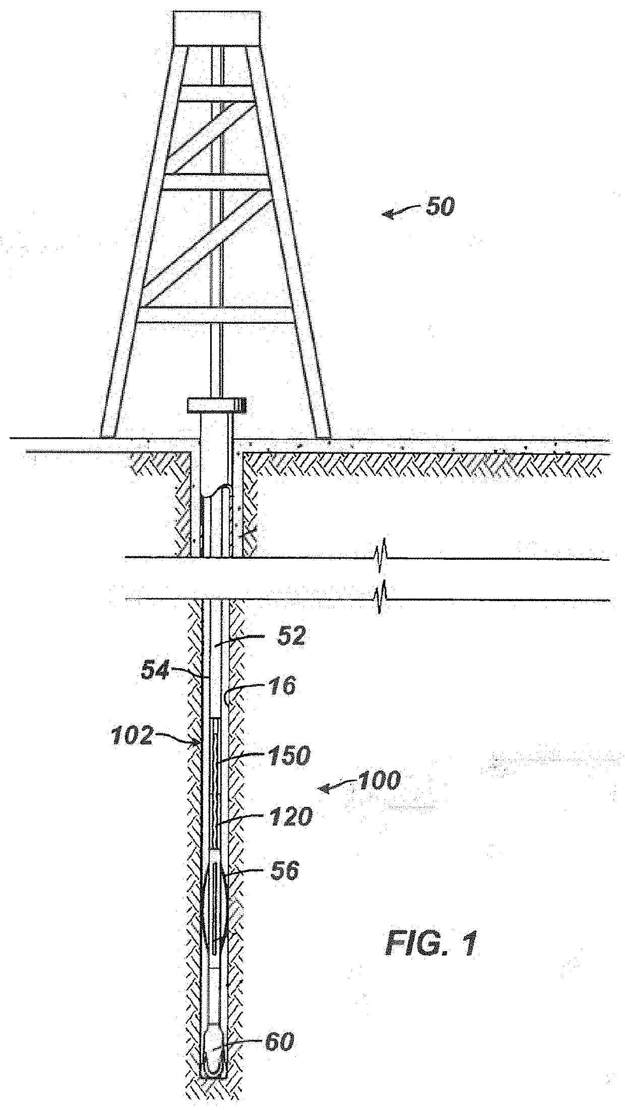
[0043]As shown in FIG. 1, for example, the progressing cavity device 100 can be used as a progressing cavity motor or positive displacement motor to drive a tool 60, such as a cutting tool, an end mill, or a drill bit, of a drilling assembly 50, which ...


PUM


Abstract

A progressing cavity device operates as a motor to impart torque to a bit. A stator of the device defines an internal profile having uphole stages with a first dimension being less than a second dimension of downhole stage. A rotor has an external profile with a constant outer dimension along its length. Disposed in the stator, the rotor defines cavities with the stator and is rotatable with pumped fluid progressing in the cavities from the uphole to downhole to transfer torque to the drive toward the downhole end. Although the rotor is subjected at the downhole end to a reactive torque from the bit, the interference fit of the rotor's constant dimension with the stator's downhole stages is less than with the uphole stages, which can mitigate issues with heat buildup in the downhole stages. The device can also operates as a progressing cavity pump.

Description

CROSS-REFERENCE TO RELATED APPLICATIONS[0001]This application is a continuation of U.S. application Ser. No. 15 / 814,541 filed 16 Nov. 2017, the contents of which is incorporated herein in its entirety.BACKGROUND OF THE DISCLOSURE[0002]A progressing cavity motor (or positive displacement motor) can be run on a tubular, drillstring, or coiled tubing to drill a borehole, mill out plugs, and perform other operations. The motor has a power section that is powered by pumped drilling fluid to rotate a tool, such as a drill bit or end mill.[0003]The power section typically has an outer steel housing, an injected elastomer stator with an internal stator profile, and a rotor with an external rotor profile. The stator profile has one more “lobe” than the rotor profile, which creates a cavity. As drilling fluid is forced through the power section, the fluid seeks the progressing cavity and causes the rotor to turn in the stator. The speed that the rotor spins is governed by the flow rate pumped...

Claims


Application Information

Patent Timeline
Patent Type & Authority Applications(United States)
IPC IPC(8): F03C2/08E21B43/12F04C13/00F04C2/107E21B4/02
CPCE21B43/126F04C13/008F03C2/08F04C2240/20F04C2240/802E21B4/02F04C2240/10F04C2/1075E21B43/12F04C13/00
Inventor PARHAR, HARJINDER SINGHCHOMETSKY, TRAVIS LEEKUHLMAN, MICHAEL W.PILGRIM, WAYNE ROBERT
Owner WEATHERFORD TECH HLDG LLC
Why Eureka
Try Eureka