Motion conversion mechanism and electric brake actuator including the same

a technology of motion conversion mechanism and electric brake actuator, which is applied in the direction of braking system, braking mechanism, etc., can solve the problems of high manufacturing cost of motion conversion mechanism, difficult processing of forming internal threads, and relatively high cost of ball screw mechanism, etc., and achieves low processing cost, high efficiency and strength, and the effect of not increasing the difficulty of processing

Active Publication Date: 2020-08-20
TOYOTA JIDOSHA KK
View PDF0 Cites 5 Cited by
  • Summary
  • Abstract
  • Description
  • Claims
  • Application Information

AI Technical Summary

Benefits of technology

[0012]Here, the number, in the axial direction, of ridges or roots of the internal thread of the cylinder, which mesh with roots or ridges of the external thread of the shaft, is defined as the number of meshing ridges. In the motion conversion mechanism according to the disclosure, even when the number of meshing ridges is relatively small, it is possible to set an axial distance between two ridges that are most separated in the axial direction, out of the ridges of the internal thread of the cylinder, which mesh with the roots of the external thread of the shaft. Thus, it is possible to make the inclination between the shaft and the cylinder relatively small without increasing the difficulty of processing to form the internal thread of the cylinder. Thus, according to the disclosure, it is possible to provide a motion conversion mechanism that has relatively high efficiency and strength and can be achieved at relatively low processing cost. In addition, according to the disclosure, it is possible to provide an electric brake actuator that has relatively high efficiency and strength and can be achieved at relatively low cost, by adopting the motion conversion mechanism according to the disclosure.

Problems solved by technology

The ball screw mechanism is relatively expensive.
Therefore, when the length of the cylinder is increased, processing for forming the internal thread becomes relatively difficult.
Thus, manufacturing costs of the motion conversion mechanism become high.
This leads to an increase in manufacturing cost of an electric brake actuator that includes such a motion conversion mechanism.

Method used


Image

  • Motion conversion mechanism and electric brake actuator including the same
  • Motion conversion mechanism and electric brake actuator including the same
  • Motion conversion mechanism and electric brake actuator including the same

Examples


Embodiment Construction

[0021]Hereinafter, a motion conversion mechanism and an electric brake actuator that are embodiments of the disclosure will be described in detail with reference to the drawings. Besides the following embodiments, the disclosure can be carried out in various forms in which various modifications and improvements are made based on the knowledge of those skilled in the art.

Electric Brake Device Including Electric Brake Actuator

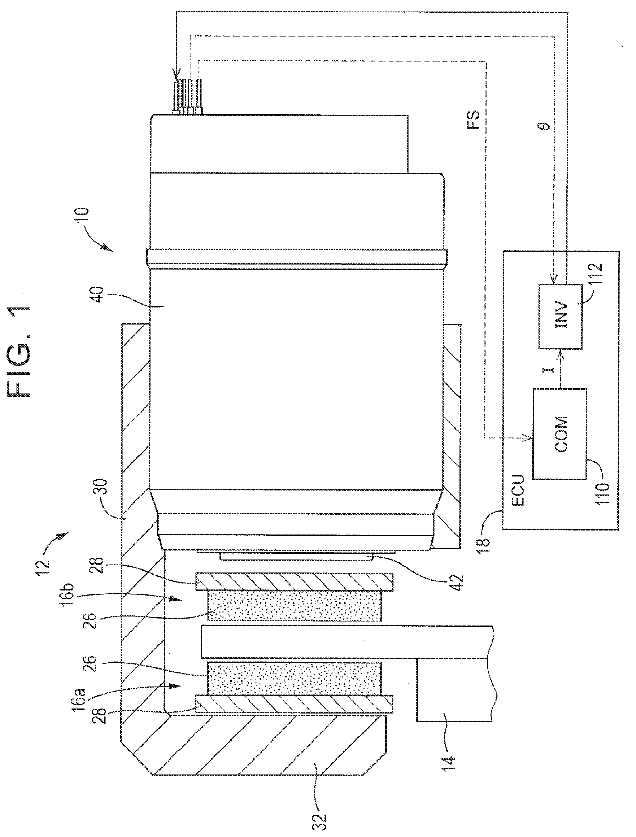
[0022]As shown in FIG. 1, an electric brake actuator 10 of the embodiment (hereinafter sometimes simply referred to as “actuator 10”) is a main component in an electric brake device. The electric brake device includes a brake caliper 12 (hereinafter sometimes simply referred to as “caliper 12”) holding the actuator 10, a disc rotor 14 serving as a rotating body that rotates with a vehicle wheel, a pair of brake pads (hereinafter sometimes simply referred to as “pads”) 16a, 16b, and an electronic control unit (hereinafter sometimes referred to as “ECU”) 18 serving...


PUM


Abstract

A motion conversion mechanism includes a shaft having an external thread and a cylinder having an internal thread that is screwed with the external thread. The motion conversion mechanism converts rotating motion of one of the shaft and the cylinder into linear motion of the other of the shaft and the cylinder. The cylinder is provided with two internal thread portions, each having the internal thread, such that a threadless portion is interposed between the two internal thread portions in an axial direction.

Description

INCORPORATION BY REFERENCE[0001]The disclosure of Japanese Patent Application No. 2019-024627 filed on Feb. 14, 2019 including the specification, drawings and abstract is incorporated herein by reference in its entirety.BACKGROUND1. Technical Field[0002]The disclosure relates to a motion conversion mechanism that converts rotating motion into linear motion. The disclosure also relates to an electric brake actuator configured such that the motion conversion mechanism converts rotating motion of the electric motor into advancing-retracting motion of a piston and a friction member is pressed against a rotating body rotating together with a wheel (for example, a brake disc) with the advancement of the piston.2. Description of Related Art[0003]There are various devices equipped with a motion conversion mechanism that converts rotating motion of one member into linear motion of another member. For example, an electric brake actuator described in Japanese Unexamined Patent Application Publ...

Claims


Application Information

Patent Timeline
Patent Type & Authority Applications(United States)
IPC IPC(8): F16H25/24B60T13/02B60T13/74
CPCB60T13/02F16H25/2214B60T13/746F16H25/2454F16D55/226F16D65/14F16D2121/24F16D2125/40F16D65/16F16H25/20B60T13/741F16D65/183F16H2025/2075
Inventor NANAHARA, MASAKI
Owner TOYOTA JIDOSHA KK
Why Eureka
Try Eureka