Trenchless methods for forming curved hole channel with steel sleeve and pipeline lifting

Active Publication Date: 2020-08-27
INFRASTRUCTURE RENEWAL INST OF SOUTHERN CHINA +1
View PDF8 Cites 1 Cited by
  • Summary
  • Abstract
  • Description
  • Claims
  • Application Information

AI Technical Summary

Benefits of technology

[0030]In the techniques for repairing the subsidence of the small-diameter concrete drainage pipeline, the new method provided by the present invention not only effectively avoids the disadvantages brought by the trench repairing, but also has the clearer goal orientation and more thorough treatment effect compared with the other trenchless repairing methods. With applying the creative trenchless method for forming the curved hole channel, the special

Problems solved by technology

When conducting the drainage pipe construction in the above areas, if the foundation is improperly treated, the uneven settlement of the pipeline foundation caused by the foundation defects easily occurs, causing the subsidence and misalignment of the pipeline joint.
If not treated in time, the joint misalignment will cause the pipeline leakage that the sewage in the pipeline leaks and the surrounding soil gradually becomes hollow, further causing the environmental pollution and the accident such as the urban road collapse, which seriously affects the ecological environment and the travel safety of the residents.
The conventional concrete drainage pipeline trench repairing method in China affects the traffic, wastes the resources and pollutes the environment, and there generally lacks the trench construction conditions due to the complex urban ground conditions.
The trenchless repairing technologies such as the insertion method, the in-situ solidification method, the winding method and the pipe splitting method are just getting started in China and ha

Method used


Image

  • Trenchless methods for forming curved hole channel with steel sleeve and pipeline lifting
  • Trenchless methods for forming curved hole channel with steel sleeve and pipeline lifting
  • Trenchless methods for forming curved hole channel with steel sleeve and pipeline lifting

Examples


first preferred embodiment

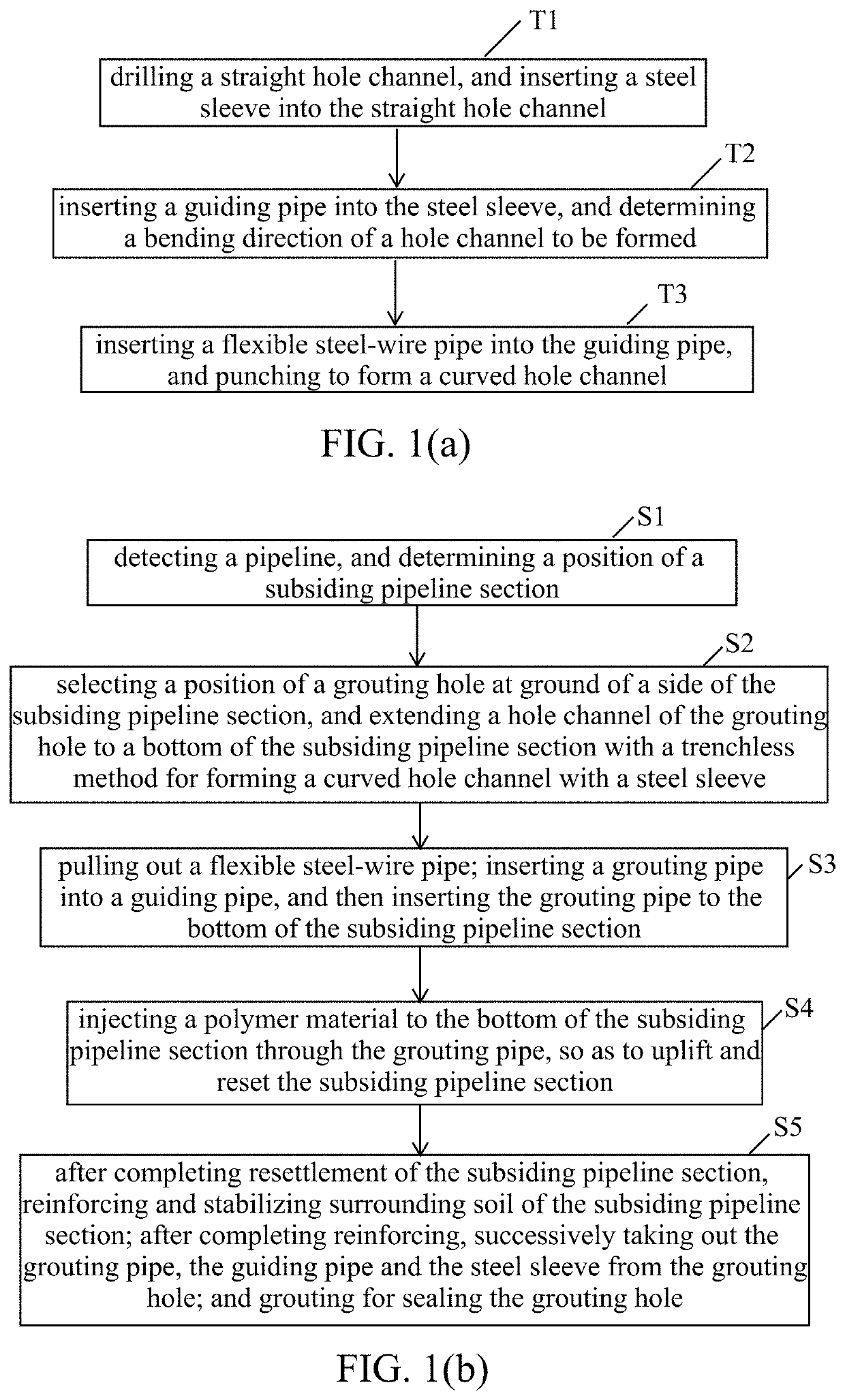
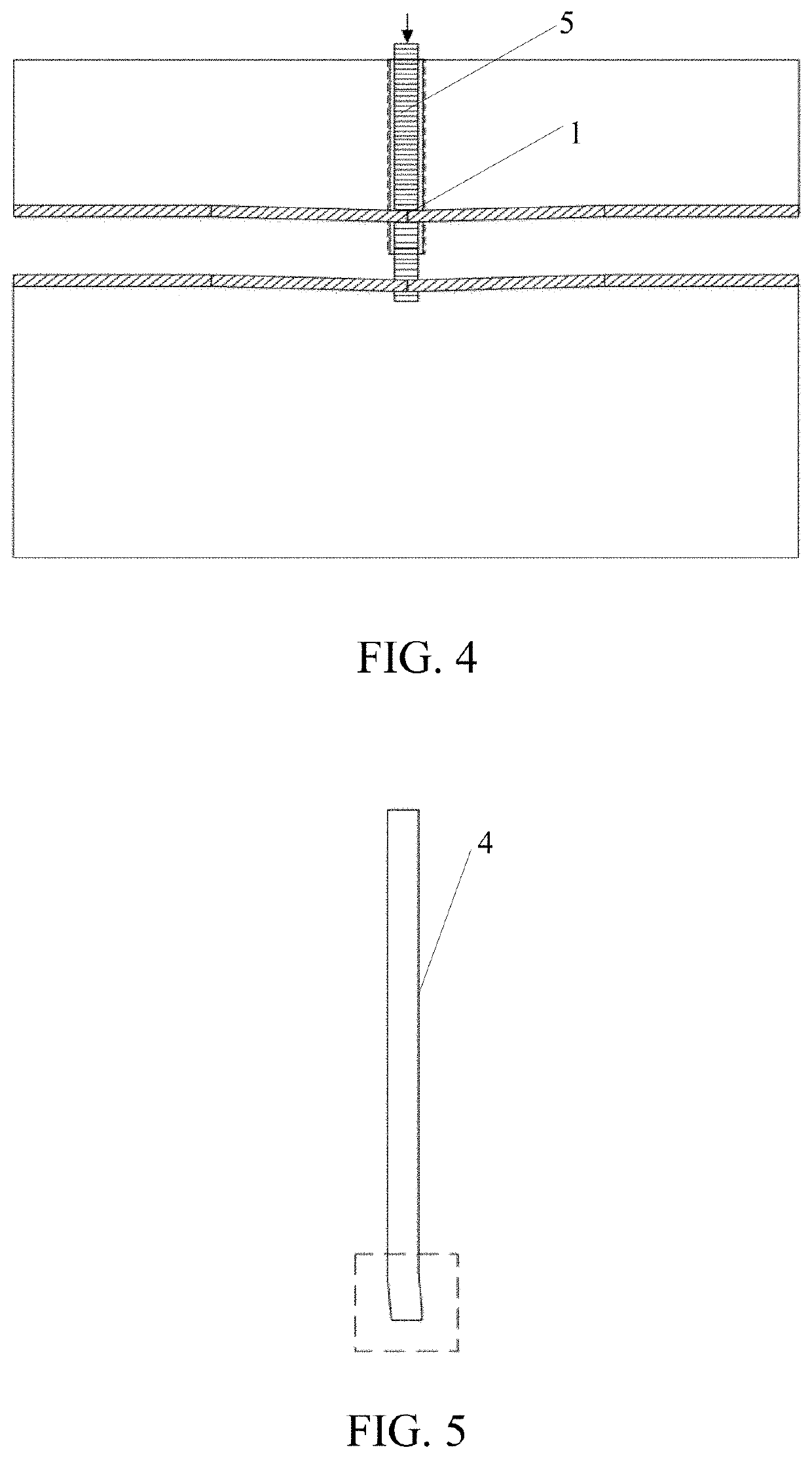
[0040]Referring to FIG. 1(a) and FIGS. 3-5, according to the first preferred embodiment of the present invention, a trenchless method for forming a curved hole channel with a steel sleeve is provided, comprising steps of:

[0041](T1) drilling a straight hole channel, and inserting the steel sleeve 3 into the straight hole channel;

[0042](T2) inserting a guiding pipe 4 into the steel sleeve 3, and determining a bending direction of a hole channel to be formed; and

[0043](T3) inserting a flexible steel-wire pipe 5 into the guiding pipe 4, and punching to form the curved hole channel.

[0044]In the first preferred embodiment, the guiding pipe is a rubber pipe with a curved tail end.

[0045]Particularly, the guiding pipe 4 plays a guiding function for punching, so as to conveniently punch to a specified position, namely a bottom of a subsiding pipeline section 1; therefore, the tail end of the guiding pipe 4 must be curved and has a definite orientation. Moreover, the steel sleeve 3 is straight...

second preferred embodiment

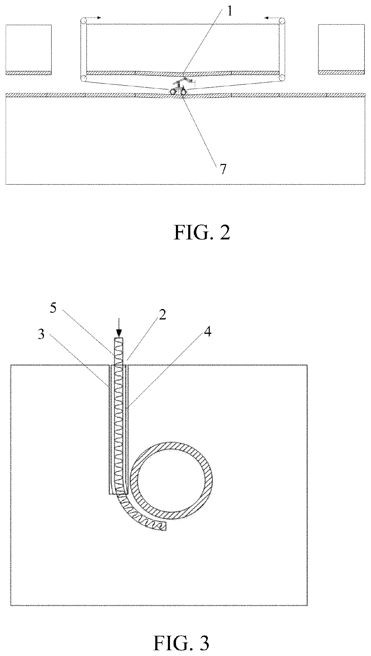
[0049]Referring to FIG. 1(a)-FIG. 7, according to the second preferred embodiment of the present invention, a trenchless method for pipeline lifting is provided, comprising steps of:

[0050](S1) detecting a pipeline, and determining a position of a subsiding pipeline section 1;

[0051](S2) selecting a position of a grouting hole 2 at ground of a side of the subsiding pipeline section 1, and extending a hole channel of the grouting hole 2 to a bottom of the subsiding pipeline section 1 with a trenchless method for forming a curved hole channel with a steel sleeve;

[0052](S3) pulling out a flexible steel-wire pipe 5; inserting a grouting pipe 6 into a guiding pipe 4, and then inserting the grouting pipe to the bottom of the subsiding pipeline section 1; and

[0053](S4) injecting a polymer material to the bottom of the subsiding pipeline section 1 through the grouting pipe 6, so as to uplift and reset the subsiding pipeline section 1.

[0054]Particularly, a specific position of the subsiding pi...


PUM


Abstract

Trenchless methods for forming a curved hole channel with a steel sleeve and pipeline lifting are provided, including steps of: (T1) drilling a straight hole channel, and inserting the steel sleeve into the straight hole channel; (T2) inserting a guiding pipe into the steel sleeve, and determining a bending direction of a hole channel to be formed; and (T3) inserting a flexible steel-wire pipe into the guiding pipe, and punching to form the curved hole channel. With applying the creative trenchless method for forming the curved hole channel, a specially-made grouting pipe is accurately inserted to a bottom of a subsiding pipeline section, so that a polymer material is conveniently injected to a bottom of a disease position. Though utilizing an expansion force generated by the polymer material, the subsiding pipeline section is uplifted, so as to realize trenchless repairing.

Description

CROSS REFERENCE OF RELATED APPLICATION[0001]The application claims priority under 35 U.S.C. 119(a-d) to CN 201910911280.4, filed Sep. 25, 2019.BACKGROUND OF THE PRESENT INVENTIONField of Invention[0002]The present invention relates to a repairing technology for concrete drainage pipeline, and more particularly to trenchless methods for forming a curved hole channel with a steel sleeve and pipeline lifting.Description of Related Arts[0003]The drainage pipeline network as one of the important urban infrastructures bears the functions of sewage discharge and drainage, and is the underground lifeline which guarantees the normal operation of the overall urban function. China has the vast territory and complex geological conditions that soil layers of silt, silty clay, soft soil and collapsible loess are widely distributed. When conducting the drainage pipe construction in the above areas, if the foundation is improperly treated, the uneven settlement of the pipeline foundation caused by ...

Claims


Application Information

Patent Timeline
IPC IPC(8): F16L7/02E21B7/00E21B19/00
CPCF16L7/02E21B19/00E21B7/00E03F3/06E03F2003/065F16L55/175F16L55/18
Inventor WANG, FUMINGFANG, HONGYUANZHAO, PENGPAN, YANHUILI, BINHE, HANG
Owner INFRASTRUCTURE RENEWAL INST OF SOUTHERN CHINA
Why Eureka
Try Eureka