Actuating system for a vacuum bottle

a vacuum bottle and actuation system technology, applied in the direction of air-break switch, high-tension/heavy-dress switch, electrical apparatus, etc., can solve the problem of the number of times the vacuum bottle is called upon

Active Publication Date: 2020-08-27
SCHNEIDER ELECTRIC IND SAS
View PDF0 Cites 0 Cited by
  • Summary
  • Abstract
  • Description
  • Claims
  • Application Information

AI Technical Summary

Problems solved by technology

Moreover, one of the issues of such an actuating system is to attain performance conforming to the standards in force for the devices in question.
Another issue is to minimize the number of times the vacuum bottle is called upon.

Method used


Image

  • Actuating system for a vacuum bottle
  • Actuating system for a vacuum bottle
  • Actuating system for a vacuum bottle

Examples


Embodiment Construction

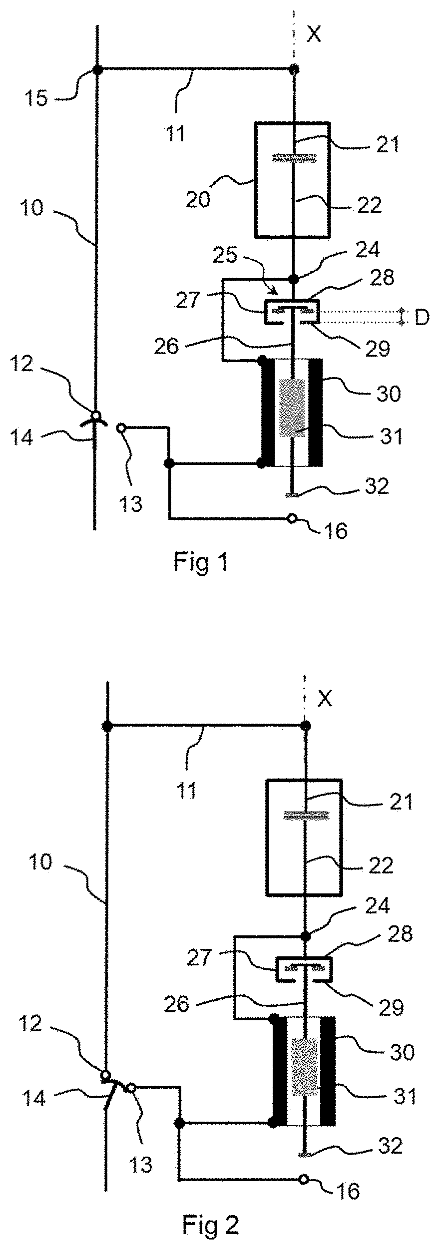
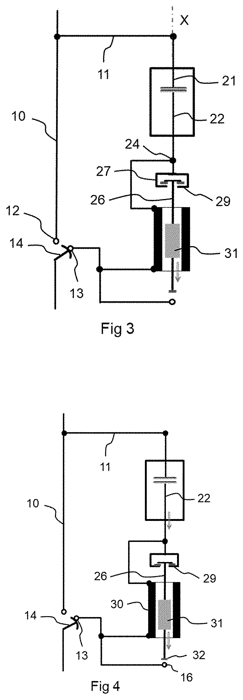
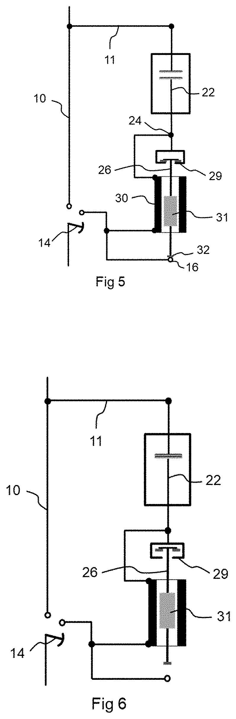
[0011]For this purpose, the invention describes a system for actuating a vacuum bottle of an electrical device, the vacuum bottle being connected in a circuit shunting a main circuit of a phase of the electrical device and comprising a movable electrode and a fixed electrode, the movable electrode being movable between a closed position in which the two electrodes are in contact with each other and an open position in which the two electrodes are separated. The actuating system comprises:[0012]a shunt contact which is connected to a movable contact of the main circuit during a movement of opening the electrical device,[0013]an electromagnet whose coil is connected between the movable electrode and the shunt contact, and whose core is mechanically linked with the movable electrode, such that the core drives the movable electrode to the open position only when the value of the current which passes through the coil reaches a predetermined threshold.

[0014]According to one feature, the c...


PUM


Abstract

A system for actuating a vacuum bottle of an electrical device, the vacuum bottle being connected in a circuit shunting a main circuit of a phase of the electrical device and comprising a movable electrode and a fixed electrode. The actuating system comprises a shunt contact which is connected to a movable contact of the main circuit during a movement of opening the electrical device, and an electromagnet whose coil is connected between the movable electrode and the shunt contact, and whose core is mechanically linked with the movable electrode, such that the core drives the movable electrode to the open position only when the value of which passes through the coil reaches a predetermined threshold.

Description

TECHNICAL FIELD OF THE INVENTION[0001]The present invention relates to a system for actuating a vacuum bottle for the purpose of opening an electrical circuit in a medium voltage or high voltage electrical device, that is to say a device operating at a voltage higher than 1000V.[0002]The invention also relates to an electrical device comprising such an actuating system for at least one of its phases. In the present document, the term electrical device indifferently includes several types of devices such as a switch, a circuit breaker, a contactor, a switch-fuse, a recloser, a disconnector, etc.PRIOR ART[0003]A medium voltage or high voltage electrical device of the type described in the document EP2182536 comprises a vacuum bottle which is placed not in the main circuit comprising the main switch of a phase of the device but in a shunt circuit in parallel with that main switch. When the main switch is closed, no current therefore flows in the vacuum bottle. The latter is called upon...

Claims


Application Information

Patent Timeline
Patent Type & Authority Applications(United States)
IPC IPC(8): H01H33/664H01H9/54
CPCH01H9/54H01H33/6647H01H33/666H01H7/12H01H33/6661
Inventor BONO, MATHIEUBONJEAN, ELOÏSE
Owner SCHNEIDER ELECTRIC IND SAS
Why Eureka
Try Eureka