Method and device in ue and base station for wireless communication

Active Publication Date: 2020-08-27
SHANGHAI LANGBO COMM TECH CO LTD
View PDF0 Cites 1 Cited by
  • Summary
  • Abstract
  • Description
  • Claims
  • Application Information

AI Technical Summary

Benefits of technology

[0066]the LBT process for a first beamforming vector and the LBT process for a second beamforming vector are designed independently to improve the efficiency of LBT, and the decision threshold and competition window are set independently according to the coverage and width of different beamforming vectors to improve the access efficiency and reduce the co-channel interference, so as to improve the overall perfo

Problems solved by technology

However, with the rapid increase of traffic, especially in some urban areas, the licensed spectrum may not meet the demand of traffic.
After introducing massive MIMO technology, when the transmitting device is configured to support multiple beamforming vectors; the wid

Method used


Image

  • Method and device in ue and base station for wireless communication
  • Method and device in ue and base station for wireless communication
  • Method and device in ue and base station for wireless communication

Examples


embodiment 1

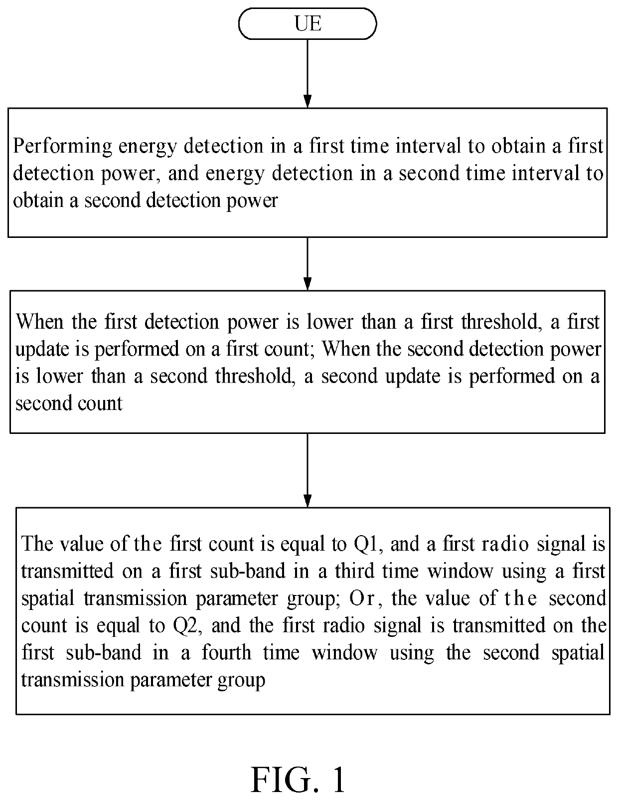
[0088]Embodiment 1 illustrates a flowchart of a first radio signal, as shown in FIG. 1.

[0089]In Embodiment 1, the UE in the present disclosure performs energy detection in a first time interval to obtain a first detection power, and energy detection in a second time interval to obtain a second detection power; when the first detection power is lower than a first threshold, a first update is performed on a first count; when the second detection power is lower than a second threshold, a second update is performed on a second count; when a value of the first count is equal to Q1, a first radio signal is transmitted on a first sub-band in a third time window using a first spatial transmit (Tx) parameter group; or, when a value of the second count is equal to Q2, the first radio signal is transmitted on the first sub-band in a fourth time window using the second spatial transmit (Tx) parameter group; the Q1 and Q2 are positive integers respectively.

[0090]In one subembodiment, the UE incl...

embodiment 2

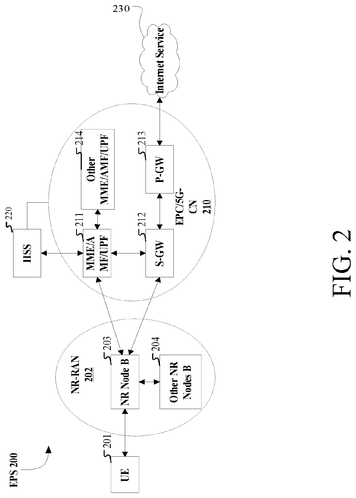
[0168]Embodiment 2 illustrates a schematic diagram of a network architecture, as shown in FIG. 2.

[0169]Embodiment 2 illustrates a schematic diagram of a network architecture according to the present disclosure, as shown in FIG. 2. FIG. 2 shows the network architecture 200 of NR 5G, Long-Term Evolution (LTE) and Long-Term Evolution Advanced (LTE-A). NR 5G or LTE network architecture 200 can be referred to as Evolved Packet System (EPS) 200 or some other appropriate term. EPS 200 may include one or more UE 201, Next Generation Radio Access Network (NG-RAN) 202, Evolved Packet Core (EPC) / 5G-Core Network (5G-CN) 210, Home Subscriber Server (HSS) 220 and Internet Service 230. EPS can be interconnected with other access networks, but these entities / interfaces are not shown for simplicity. As shown in the figure, EPS provides packet switching services, while those skilled in the art will readily understand that various concepts presented throughout the disclosure can be extended to network...

embodiment 3

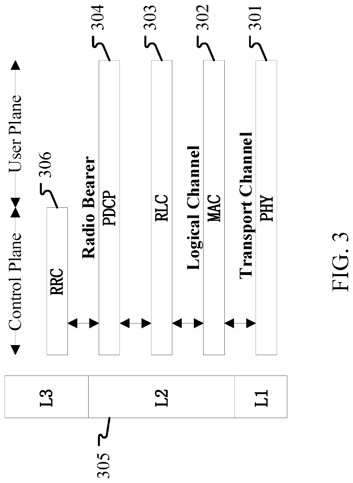
[0176]Embodiment 3 illustrates a schematic diagram of an example of a radio protocol architecture of a user plane and a control plane according to one embodiment of the present disclosure, as shown in FIG. 3.

[0177]FIG. 3 is a schematic diagram illustrating an embodiment of a radio protocol architecture for a user plane and a control plane. FIG. 3 shows a radio protocol architecture for a UE and a base station (gNB or eNB) in three layers: Layer 1, 2 and 3. Layer 1 (L1) is the lowest layer and implements various physical layer (PHY) signal processing functions. L1 will be called PHY 301 in this article. 305, Layer 2 (L2) is above PHY 301 and is responsible for the link between UE and gNB through PHY 301. In the user plane, 305, L2 includes Medium Access Control (MAC) sublayer 302, Radio Link Control (RLC) sublayer 303 and Packet Data Convergence Protocol (PDCP) sublayer 304, which terminate at the gNB on the network side. Although not shown, UE may have several upper layers above 305...


PUM


Abstract

The present disclosure provides a method and a device in a User Equipment (UE) and a base station used for wireless communication. The UE performs energy detection in a first time interval to obtain a first detection power, and performs energy detection in a second time interval to obtain a second detection power; a value of the first count is obtained according to the relationship between the first detection power and a first threshold, and a value of the second count is obtained according to the relationship between the second detection power and a second threshold. The present disclosure optimizes the selection of beamforming-based transmission parameter group by establishing a relationship between a spatial transmit parameter group adopted by the first radio signal, a length of a time window for energy detection and multiple thresholds, thereby improving overall system performance.

Description

CROSS REFERENCE TO RELATED APPLICATIONS[0001]This application is a continuation of International Application No. PCT / CN2017 / 113310, filed on Nov. 28, 2017, claiming the priority benefit of International Application PCT / CN2017 / 113310, filed on Nov. 28, 2017, the full disclosure of which is incorporated herein by reference.BACKGROUNDTechnical Field[0002]The present disclosure relates to transmission methods and devices in wireless communication systems, and in particular to a communication method and device that support data transmission on Unlicensed Spectrum.Related Art[0003]In the traditional 3rd Generation Partner Project (3GPP) Long-term Evolution (LTE) system, data transmission can only occur on the licensed spectrum. However, with the rapid increase of traffic, especially in some urban areas, the licensed spectrum may not meet the demand of traffic. The communication on the unlicensed spectrum in Release 13 and Release 14 is introduced by the cellular system and is used for the...

Claims


Application Information

Patent Timeline
IPC IPC(8): H04W72/04H04L5/00H04L1/00H04W24/10H04W24/08H04W16/14
CPCH04L5/0082H04W24/10H04L5/0051H04L1/0004H04W16/14H04W24/08H04W72/0473H04B7/06H04W74/0808H04L5/0023
Inventor JIANG, QIZHANG, XIAOBO
Owner SHANGHAI LANGBO COMM TECH CO LTD
Why Eureka
Try Eureka