
Glass laminate with printed obscuration having superior strength and optical quality

a technology of printed obscuration and glass laminate, which is applied in the direction of transportation and packaging, coatings, chemistry apparatuses and processes, etc., to achieve the effects of reducing residual stress, high yield and high strength

Pending Publication Date: 2020-09-17
AGP AMERICA
View PDF3 Cites 1 Cited by
  • Summary
  • Abstract
  • Description
  • Claims
  • Application Information

AI Technical Summary

Benefits of technology

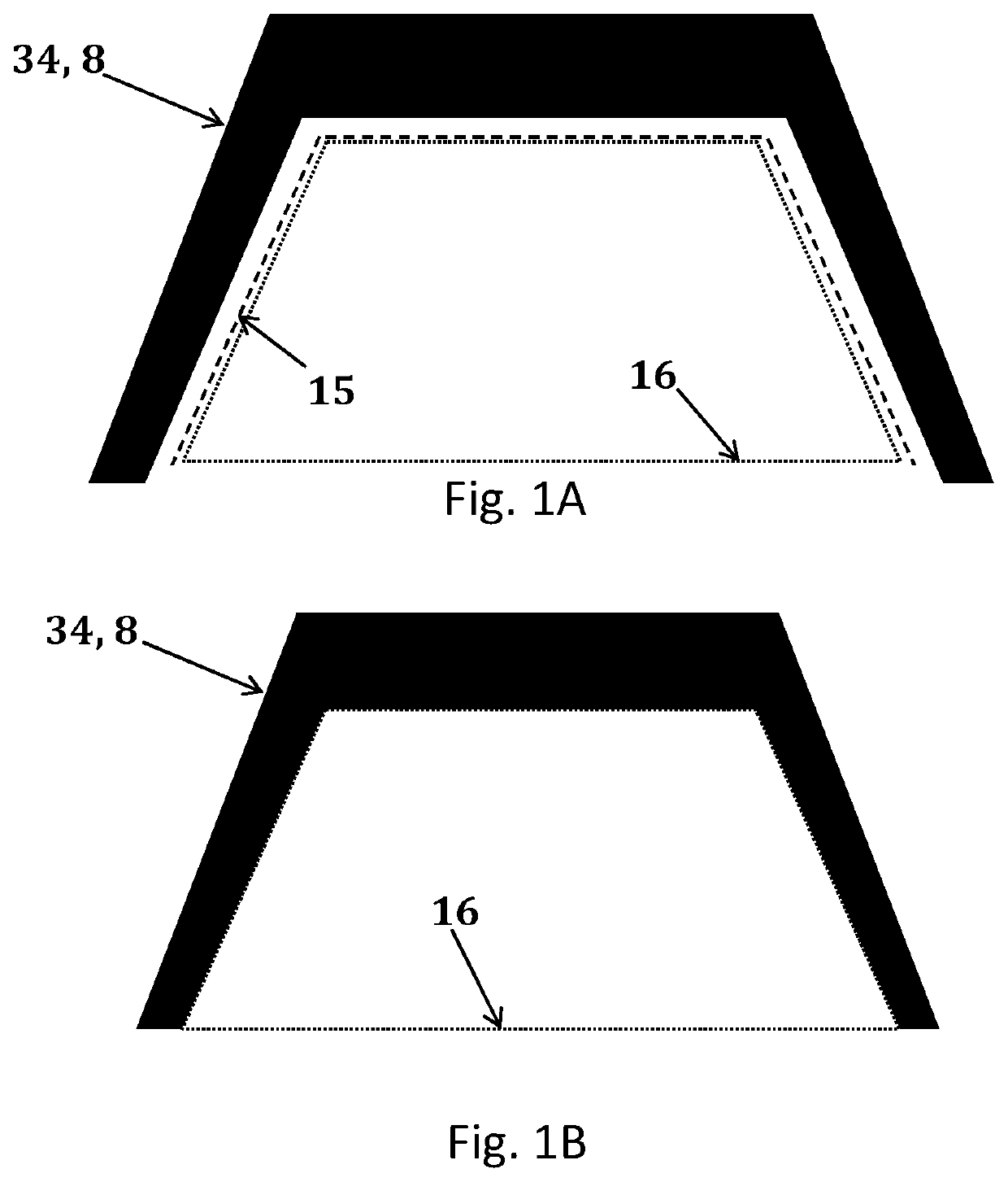
The invention is a type of automotive glazing that has a layer of opaque material printed on one or more of its surfaces, either during the bending process or afterward. This is done by using commercially available inkjet or screen printing technology, rather than traditional frit printing. The printing is done on the glass's camera field of view or edges, which are not usually obscured. The technique results in stronger and higher quality glazing, better optics, and reduced distortion and breakage. It also increases the yield of the glass during bending and lamination.

Problems solved by technology

The first surface of the glass is generally not used as contact with the wiper blades is detrimental to both the obscuration and the wiper blades.

Method used


Image

  • Glass laminate with printed obscuration having superior strength and optical quality
  • Glass laminate with printed obscuration having superior strength and optical quality
  • Glass laminate with printed obscuration having superior strength and optical quality

Examples


embodiment 1

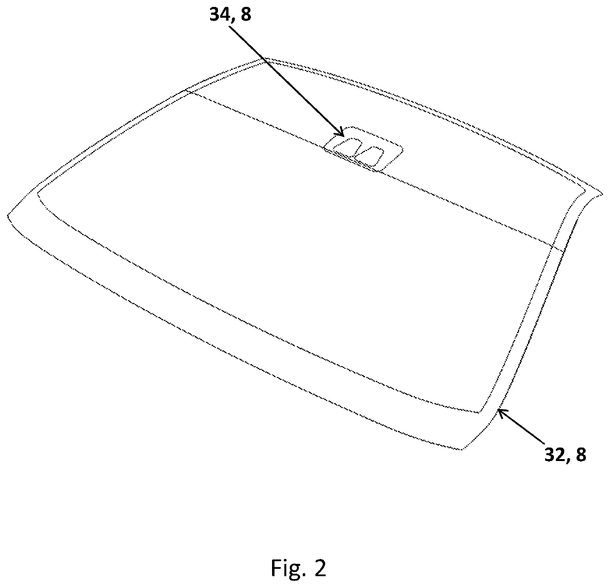
[0103]The windshield of FIG. 8 comprising a ceramic frit black band 32 and a camera obscuration 34 printed by means of an organic black ink after heating and bending of the glass and printed by means of a mask and spray system on the second surface of glass 102.

embodiment 2

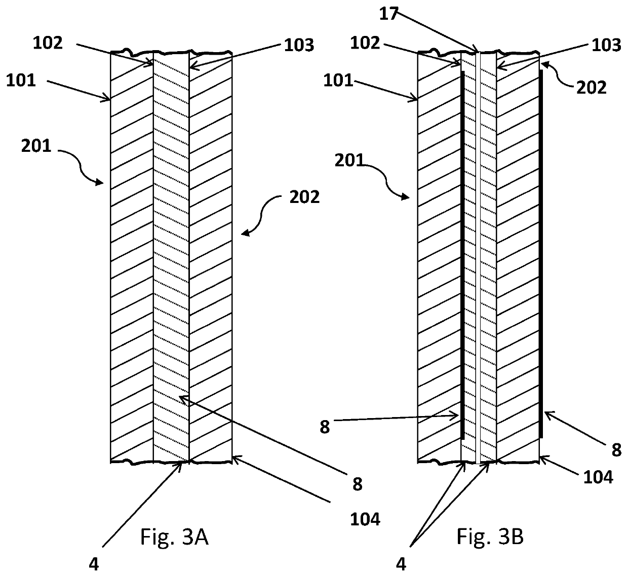
[0104]The windshield of FIG. 8 comprising a ceramic frit black band 32 and a camera obscuration 34 printed by means of an organic black ink after heating and bending of the glass printed by means of a mask and spray system on the second surface of glass 102 and fourth surface of glass 104.

embodiment 3

[0105]The windshield of FIG. 8 comprising a ceramic frit black band 32 and a Camera obscuration 34 printed by means of an organic black ink after heating and bending of the glass printed by means of a mask and spray system on the second surface of glass 102 and fourth surface of glass 104 and further comprising a wedge / shaped plastic interlayer.


PUM

PropertyMeasurementUnit
Angleaaaaaaaaaa
Angleaaaaaaaaaa
Angleaaaaaaaaaa

Abstract

The use of camera-based safety systems is growing at a rapid rate in modern automobiles. At the same time, windshields, where many of the cameras are mounted, are becoming larger and more complex in shape. As the industry moves towards vehicles with full autonomous capability, the number of cameras required and the resolution of the cameras are both increasing. However, the optical quality of the windshield is less than optimal. One of the problems is caused by the typical black enamel frit that is printed on the glass, prior to heating and bending, to hide or obscure the camera hardware. The abrupt thermal gradients during bending, caused by the heat absorbing black frit, result a high level of distortion in the camera field of view. The object of this invention is to provide a laminated automotive glazing having an obscuration area produced by creating an obscuration, after heating and bending of the glass, by printing the obscuration on one or more of the surfaces of the bent glass in or near the camera field of view (camera obscuration) or / and in the edges of the windshield (black band) rather than printing and firing an enamel frit on the glass. This results in a laminate having superior optical quality, higher strength and a lower probability of breakage as compared to a laminate with a black enamel frit obscuration.

Description

FIELD OF THE INVENTION[0001]The presently disclosed invention is directed to a laminated automotive glazing having a camera obscuration which provides for a field of view having superior optical quality and strength as well as the method used to create said glazing.BACKGROUND OF THE INVENTION[0002]Black enamel frit obscurations are commonly printed on laminated and tempered automotive safety glazing. These obscurations have multiple functional and aesthetic requirements. The obscuration must be substantially opaque. This is needed to prevent the adhesive, used to mount the glazing to the vehicle, from being seen from the outside of the vehicle and to protect the adhesive from the harmful effects of ultra-violet. The obscuration also serves this same function for components attached to the inside surface of the glazing. On heated and coated glazing, the obscuration is used to hide the edge of the coating, bus bars, leads and any other items that would detract from the appearance of t...

Claims


Application Information

Patent Timeline
IPC IPC(8): B32B17/10
CPCB32B17/10761B32B17/10174B32B2605/006B32B2605/08B32B17/10788B32B2315/08B32B17/10348B32B17/10266B32B17/10036B32B17/10091B32B17/10137B32B17/10568B32B17/10706B32B17/10743B32B17/1077B32B1/00B32B17/10005B32B2367/00
Inventor MANNHEIM ASTETE, MARIO ARTUROVOELTZEL, CHARLES S.GRANADOS CARO, LAURASARMIENTO SANTOS, ANDRES FERNANDOMENDOZA CARRANZA, ELENA K.
Owner AGP AMERICA
Learn More