Check patentability & draft patents in minutes with Patsnap Eureka AI!

Plasma ignition circuit

a technology of ignition circuit and plasma, which is applied in the direction of plasma technique, electrical equipment, electric discharge tubes, etc., can solve the problems of small plasma processing window, unwanted sputtering and damage to the substrate surface, and ions formed in the plasma to bombard and possibly damage the exposed surfaces of the substrate or chamber component,

Active Publication Date: 2020-09-17
APPLIED MATERIALS INC
View PDF0 Cites 0 Cited by
  • Summary
  • Abstract
  • Description
  • Claims
  • Application Information

AI Technical Summary

Benefits of technology

The patent describes a plasma ignition circuit and a processing chamber with the circuit. The circuit includes a transformer and a control switch that can apply a secondary RF voltage to a remote plasma source to ignite a plasma. The circuit can sense the secondary RF voltage and apply or discontinue the voltage based on the sensed voltage. The technical effect of the patent is to provide a reliable and efficient method for igniting a plasma within a remote plasma source.

Problems solved by technology

Conventional plasma processing chamber designs in which the generated plasma is disposed over the substrate surface can cause unwanted sputtering and damage to the substrate surface due to the interaction of electrons and ions formed in the plasma with the substrate surface.
The formed net charge causes electrons and / or ions formed in the plasma to bombard and possibly damage the exposed surfaces of the substrate or chamber component.
However, conventional remote plasma sources typically utilize microwave, capacitively coupled, or inductively coupled energy sources that have a narrow plasma generating region, which causes these devices to have a smaller than desirable plasma processing window that limits the range of energies of the formed gas radicals and gas ion that are formed in the plasma generating region of the conventional RPS.
Conventional remote plasma sources are generally not able to tune power delivered to the plasma without also altering other process conditions, and undesirably may employ ignition voltages that are large enough to cause arcing within the chamber.

Method used


Image

  • Plasma ignition circuit
  • Plasma ignition circuit
  • Plasma ignition circuit

Examples


Embodiment Construction

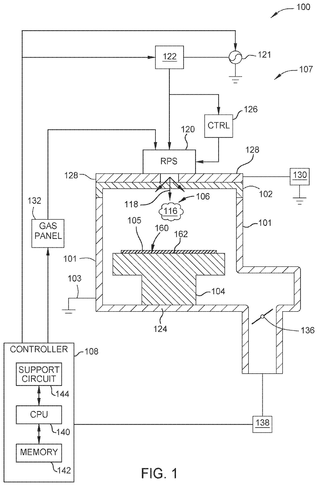
[0027]A high voltage plasma ignition circuit configured to ignite a plasma in a remote plasma source (RPS) fluidly coupled to an internal volume of a processing chamber is disclosed. The plasma ignition circuit provides consistent and reliable plasma ignition, and fast detection of plasma formation. Once the plasma is ignited, the plasma ignition circuit detects a drop in a value of impedance of the plasma, which turns the plasma ignition circuit off quickly and automatically.

[0028]Consistent plasma ignition provided by the ignition circuit provides improved process reliability and performance. The plasma ignition circuit avoids unnecessary applied voltage overshoot and long duration of applied high voltage. The plasma ignition circuit ignites the plasma consistently and avoids applying high voltage for an extended period of time. Thus, the ignition circuit improves chamber performance and prevents chamber arcing.

[0029]FIG. 1 is a schematic cross-sectional view of a processing chamb...


PUM


Abstract

A plasma ignition circuit includes a transformer having a primary coil configured to couple an RF power supply. A first secondary coil is configured to couple a remote plasma source (RPS), and a second secondary coil. The plasma ignition circuit further includes a control switch having an input configured to couple the second secondary coil and an output configured to capacitively couple the RPS and a switch controller. The switch controller is configured to upon sensing a secondary RF voltage applied to the second secondary coil in response to an RF voltage applied by RF power supply to the primary coil, enable the control switch to capacitively apply the secondary RF voltage to the RPS to ignite a plasma within the RPS. Upon sensing a drop in plasma impedance when the plasma is ignited, disable the control switch to discontinue applying the secondary RF voltage to the RPS.

Description

CROSS-REFERENCE TO RELATED APPLICATIONS[0001]This application claims benefit of U.S. provisional patent application Ser. No. 62 / 817,833, filed Mar. 13, 2019, which is herein incorporated by reference.BACKGROUNDField[0002]Examples of the present disclosure generally relate to an inductively-coupled remote plasma source (RPS) for a processing chamber, and more particularly, to a plasma ignition circuit for igniting a plasma from processing gases circulated in the processing chamber using the RPS.Description of the Related Art[0003]Plasma processing chambers are regularly utilized in various electronic device fabrication processes, such as etching processes, chemical vapor deposition (CVD) processes, and other processes related to the manufacture of electronic devices on substrates. Many ways have been employed to generate and / or control the plasma density, shape, and electrical characteristics in processing chambers, such as capacitively or inductively coupled RF sources commonly used...

Claims


Application Information

Patent Timeline
Patent Type & Authority Applications(United States)
IPC IPC(8): H01J37/32H05H1/36
CPCH01J37/32091H05H1/36H01J37/32174H01J37/32082H01J37/32183H01J37/3299H01J37/32935
Inventor PRATT, TERYLWANG, RONGPINGMAO, GUOMINCHUANG, ANDY
Owner APPLIED MATERIALS INC
Features
  • R&D
  • Intellectual Property
  • Life Sciences
  • Materials
  • Tech Scout
  • Unparalleled Data Quality
  • Higher Quality Content
  • 60% Fewer Hallucinations
Learn More