Sensor with compensation circuit
a compensation circuit and sensor technology, applied in the direction of ac/dc measuring bridges, instruments, code conversion, etc., can solve the problems of interference and output data also being affected by interference, and the addition result is larger than the effect of adding results
- Summary
- Abstract
- Description
- Claims
- Application Information
AI Technical Summary
Benefits of technology
Problems solved by technology
Method used
Image


Examples
first embodiment
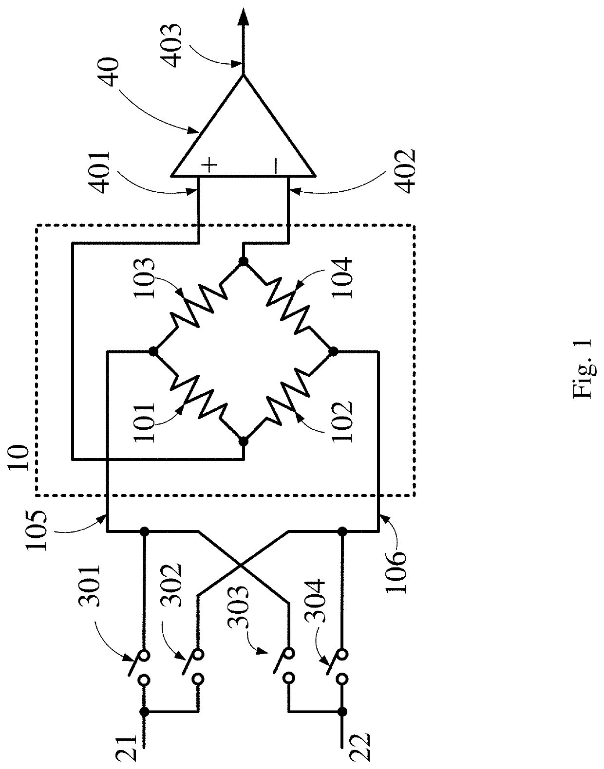
[0030]the present invention is disclosed in FIG. 1. It shows a sensor with compensation circuit. The sensor with compensation circuit comprises a sensor 10, four switches and an amplifier 40. The sensor 10 comprises a first input 105, a second input 106, a first output 107 and a second output 108. The first switch 301 connects between the first power source 21 and the first input 105. The second switch 302 connects between the first power source 21 and the second input 106. The third switch 303 connects between the second power source 22 and the first input 105. The fourth switch 304 connects between the second power source 22 and the second input 106. The amplifier 40 has a positive amplifier input 401 and a negative amplifier input 402, separately connected to the first output 107 and the second output 108. In other words, the first output 107 can either be connected to the positive amplifier input 401 or the negative amplifier input 402, and so does the second output 108. For exa...
second embodiment
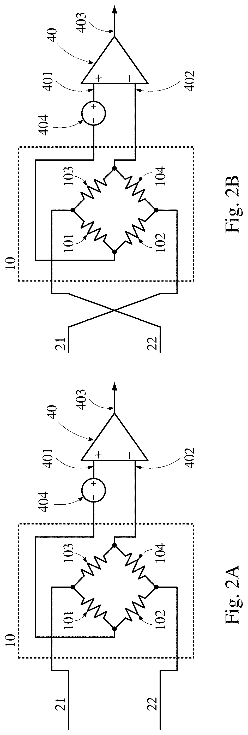
[0048]the present invention is disclosed in FIG. 3. It shows a sensor with compensation circuit. The sensor with compensation circuit comprises a sensor 10, four switches and an amplifier 40. The sensor 10 comprises a first input 105, a second input 106, a first output 107 and a second output 108. Wherein the first power source 21 connects to the first input 105 and the second power source 22 connects to the second input 106. The first switch 301 connects between the first output 107 and the positive amplifier input 401. The second switch 302 connects between the first output 107 and the negative amplifier input 402. The third switch 303 connects between the second output 108 and the positive amplifier input 401. The fourth switch 304 connects between the second output 108 and the negative amplifier input 402. In addition, the voltage of the amplifier output 403 is generated according to the voltage difference between the positive amplifier input 401 and the negative amplifier input...
PUM
 Abstract
Description
Claims
Application Information
 - R&D
- Intellectual Property
- Life Sciences
- Materials
- Tech Scout
- Unparalleled Data Quality
- Higher Quality Content
- 60% Fewer Hallucinations
Browse by: Latest US Patents, China's latest patents, Technical Efficacy Thesaurus, Application Domain, Technology Topic, Popular Technical Reports.
© 2025 PatSnap. All rights reserved.Legal|Privacy policy|Modern Slavery Act Transparency Statement|Sitemap|About US| Contact US: help@patsnap.com