Motor drive control device, motor system, and air blowing device

a control device and motor technology, applied in the direction of efficient regulation technologies, mechanical equipment, machines/engines, etc., can solve the problems of inability to ensure the time for detecting phase currents other than those of u-phases, and the inability to ensure the time for detecting phase currents

Active Publication Date: 2020-09-24
NIPPON DENSAN CORP
View PDF1 Cites 1 Cited by
  • Summary
  • Abstract
  • Description
  • Claims
  • Application Information

AI Technical Summary

Benefits of technology

[0007]According to an aspect of the disclosure, there is provided a motor drive control device controlling driving of a motor using a PWM inverter outputting a three-phase AC voltage to the motor and detecting current values of respective phases of the three-phase AC voltage by controlling turning on-off of an upper arm switching element and a lower arm switching element of the PWM inverter using a PWM pulse. The motor drive control device includes a phase voltage command part which outputs phase voltage commands for the respective phases of the three-phase AC voltage, and a PWM control part which generates the PWM pulse based on a carrier signal cyclically repeating rising and falling and the phase voltage commands. The PWM control part generates a first PWM pulse based on a largest phase voltage command, of the phase voltage commands, for a largest phase having a largest phase voltage command value, and the carrier signal. Moreover, the PWM control part causes the first PWM pulse to be at a level for turning off the lower arm switching element for the largest phase throughout an entire first period that is one of a rising period and a falling period of the carrier signal. In addition, the PWM control part generates a second PWM pulse based on a smallest phase voltage command, of the phase voltage commands, for a smallest phase having a smallest ph

Problems solved by technology

However, if time intervals of the rising edges in the respective transistors to be turned on become closer, there is concern that a time for detecting phase currents may not be able to be ensured.
For example, in a sinusoidal three-phase AC voltage, since a differenc

Method used


Image

  • Motor drive control device, motor system, and air blowing device
  • Motor drive control device, motor system, and air blowing device
  • Motor drive control device, motor system, and air blowing device

Examples


embodiment

1. Embodiment

[0029]

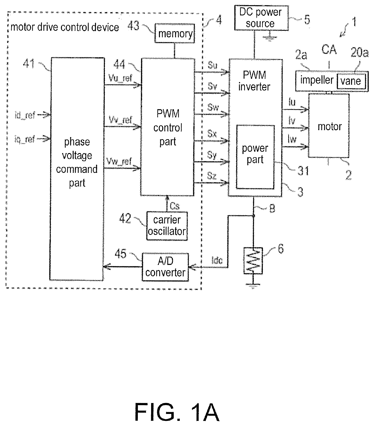
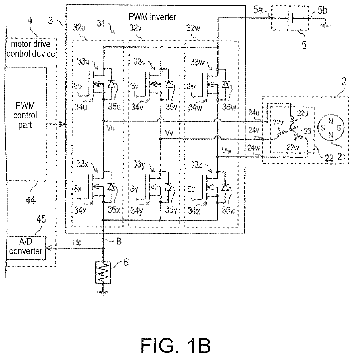
[0030]FIG. 1A is a block diagram illustrating a constitutive example of an air blowing device 1. FIG. 1B is a circuit diagram illustrating a constitutive example of a part of the air blowing device 1. The air blowing device 1 is an example of a motor drive control system and includes an impeller 2a, the motor 2, a PWM inverter 3 having a power part 31, a motor drive control device 4, a DC power source 5, and a shunt resistor 6.

[0031]The impeller 2a is attached to the motor 2 and can rotate in accordance with driving of the motor 2. The impeller 2a has a vane 20a which is rotatable about a central axis CA extending in an up-down direction.

[0032]The motor 2 rotates the vane 20a of the impeller 2a. A three-phase AC voltage is applied to the motor 2 by the PWM inverter 3. For example, the motor 2 is a three-phase brushless DC motor (BLDC motor). More specifically, as illustrated in FIG. 1B, the motor 2 includes a rotor 21 and a stator 22. A permanent magnet is provide...


PUM


Abstract

A motor drive control device controls driving of a motor by performing PWM control of turning on-off of an arm switching element of a PWM inverter outputting a three-phase AC voltage to the motor, and detects current values of respective phases of the three-phase AC voltage. The motor drive control device turns off a lower arm switching element for a largest phase by causing a first PWM pulse based on a largest phase voltage command and a carrier signal throughout an entire first period during which the carrier signal rises or falls to be at a low level. The motor drive control device turns on a lower arm switching element for a smallest phase by causing a second PWM pulse based on a smallest phase voltage command and the carrier signal throughout an entire second period during which the carrier signal rises or falls to be at a high level.

Description

CROSS-REFERENCE TO RELATED APPLICATION[0001]This application claims the priority benefit of Japan Patent Application No. 2019-055327, filed on Mar. 22, 2019. The entirety of the above-mentioned patent application is hereby incorporated by reference herein and made a part of this specification.BACKGROUNDTechnical Field[0002]The disclosure relates to a motor drive control device, a motor system, and an air blowing device.Description of Related Art[0003]In the related art, devices performing PWM control of a motor driven using a three-phase AC voltage output from an inverter are known. In the related art, control devices having an inverter circuit in which two transistors connected in series are connected in parallel in three rows are used, and these control devices perform A / D conversion of phase currents of respective phases in a three-phase AC voltage output from the inverter circuit to the motor and detect the converted currents in order to correct a current error between a phase c...

Claims


Application Information

Patent Timeline
IPC IPC(8): H02P27/08H02M7/5387F04D25/06
CPCF04D25/06H02P27/08H02M7/53871F04D27/004H02M7/53875H02M7/5395Y02B30/70H02M1/0009
Inventor UE, KAZUMASAMATSUZAKI, KAZUYA
Owner NIPPON DENSAN CORP
Why Eureka
Try Eureka