Optical particle sensor

a particle sensor and optical technology, applied in the field of laser sensor or laser sensor module, can solve the problems and the inability to assign an emission direction to the determined self-mixing interference signal, so as to reduce the size, complexity and therefore the cost of particle sensors, and achieve sufficient accuracy. , the effect of increasing the size and cost of such particle sensors

Active Publication Date: 2020-10-01
TRUMPF PHOTONIC COMPONENTS GMBH
View PDF0 Cites 7 Cited by
  • Summary
  • Abstract
  • Description
  • Claims
  • Application Information

AI Technical Summary

Benefits of technology

[0008]The number of detected particles determined by means of optical sensing techniques depends on the relative velocity of the particles with respect to the optical beam. It is therefore necessary to determine the velocity of the particles in order to determine the corresponding particle density. In the general case of an unknown wind direction multiple self-mixing laser sensors pointing in different directions, preferably orthogonally placed, must be used. Each of the self-mixing laser sensors emits a laser beam in the corresponding direction and a self-mixing interference signal is generated as soon as the laser beam is reflected at a particle such that at least a part of the reflected laser beam re-enters a laser cavity of the corresponding self-mixing laser sensor. A velocity component of the particle parallel to the emission direction of the laser beam can be determined by means of the self-mixing interference signal. Three self-mixing laser sensors emitting laser light in linear independent directions (preferably orthogonal directions as x, y, and z) are therefore necessary to determine the velocity vector of the particle flow. In other configurations, the direction of the particle flow has to be fixed with respect to the self-mixing laser sensor or an artificial particle flow has to be generated by means of, for example, a movable mirror such that the influence of the wind speed may be negligible. Especially movable mechanical parts as an oscillating mirror increase the size and cost of such particle sensor.
[0009]The laser sensor module with one common detector for detecting self-mixing interference signals of at least two lasers decrease the size, the complexity and therefore the cost of particle sensors. The detector is not arranged to differentiate which of the laser cavities generates the self-mixing interference signal. It is thu

Problems solved by technology

Especially movable mechanical parts as an oscillating mirror increase the size and cost of such particle sensor.
It is thus not possible to assign an emission direction to the determined

Method used


Image

  • Optical particle sensor
  • Optical particle sensor
  • Optical particle sensor

Examples


Embodiment Construction

[0071]Various embodiments of the invention will now be described by means of the Figures.

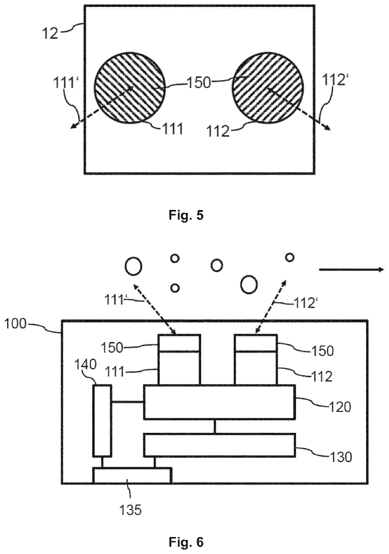
[0072]Self-mixing interference is used for detecting movement of and distance to an object. Background information about self-mixing interference is described in “Laser diode self-mixing technique for sensing applications”, Giuliani, G.; Norgia, M.; Donati, S. & Bosch, T., Laser diode self-mixing technique for sensing applications, Journal of Optics A: Pure and Applied Optics, 2002, 4, S. 283-S. 294 which is incorporated by reference. Detection of movement of a fingertip relative to a sensor in an optical input device is described in detail in International Patent Application No. WO 02 / 37410 which is incorporated by reference. The principle of self-mixing interference is discussed based on the examples presented in International Patent Application No. WO 02 / 37410. A diode laser having a laser cavity is provided for emitting a laser, or measuring, beam. At its upper side, the device is provided w...


PUM


Abstract

The invention describes a laser sensor module. The laser sensor module comprises at least a first laser (111) being adapted to emit a first measurement beam (111′) and at least a second laser (112) being adapted to emit a second measurement beam (112′). The laser sensor module further comprises an optical device (150) being arranged to redirect the first measurement beam (111′) and the second measurement beam (112′) such that the 5 first measurement beam (111′) and the second measurement beam enclose an angle between 45° and 135°. The laser sensor module comprises one detector (120) being adapted to determine at least a first self-mixing interference signal of a first optical wave within a first laser cavity of the first laser (111) and at least a second self-mixing interference signal of a second optical wave within a second laser cavity of the second laser (112). This configuration 10 enables determination of an average velocity of the particles despite of the fact that it is not possible to determine the components of the velocity vector. The introduced error by means of statistical variations is acceptable because the number of detected particles scales with the cubic root of the particle velocity. The invention further describes a particle sensor (100) comprising such a laser sensor module, a corresponding method and computer program 15 product. The invention enables a simple and low-cost particle sensor (100) for detecting small particles based on laser self-mixing interference.

Description

FIELD OF THE INVENTION[0001]The invention relates to a laser sensor or laser sensor module using self-mixing interference for particle density detection, a related method of particle density detection and a corresponding computer program product. The invention further relates to a device comprising such a laser sensor or laser sensor module.BACKGROUND OF THE INVENTION[0002]CN102564909 A discloses a laser self-mixing multi-physical parameter measurement method and a laser self-mixing multi-physical parameter measurement device for atmospheric particulate matter. The laser self-mixing multi-physical parameter measurement device comprises a microchip laser, a collimating lens, a beam splitter, converging lenses, a photodetector, an amplifier, a data acquisition card and a spectrum analyzer. The described methods and devices are complicated and expensive.SUMMARY OF THE INVENTION[0003]It is an object of the present invention to provide an improved laser sensor module for particle density...

Claims


Application Information

Patent Timeline
IPC IPC(8): G01N15/02G01N15/14H01S5/183G01S17/87
CPCG01N15/0205G01N2015/0003H01S5/183G01N15/1434G01N2015/1454G01P5/26G01S17/58G01S7/4916H01S5/0028H01S5/0656H01S5/423G01S17/87G01S7/4812H01S5/02255Y02A90/10
Inventor SPRUIT, JOHANNES HENRIKUS MARIAJUTTE, PETRUS THEODORUSVAN DER LEE, ALEXANDER MARCMOENCH, HOLGER JOACHIMHELLMIG, JOACHIM WILHELM
Owner TRUMPF PHOTONIC COMPONENTS GMBH
Why Eureka
Try Eureka