
Solids washing in oil and/or gas production

a technology of oil and gas production and solids washing, which is applied in the direction of solid separation, cleaning using liquids, and borehole/well accessories, etc., can solve the problems of increasing the amount of solids increasing the stress in the matrix, and increasing the amount of sand being swept into the production well, etc., to achieve the effect of safe disposal

Active Publication Date: 2020-10-15
FOURPHASE
View PDF0 Cites 7 Cited by
  • Summary
  • Abstract
  • Description
  • Claims
  • Application Information

AI Technical Summary

Benefits of technology

The patent describes a device for detecting oil content in a sand / water mixture. The device has a chamber with two exits, each with valves that can be opened and closed by a controller. One exit connects to a pump that sends the sand / water mixture back to the vessel for further washing, while the other exit carries cleaned solids particles safely out of the device. The technical effect of this patent is to provide a more efficient and automated method for detecting oil content in a sand / water mixture, which can help to improve the overall efficiency and safety of the oil well drilling process.

Problems solved by technology

Such changes can result in increased stress in the matrix so that mechanical failure can occur, resulting in larger amounts of solids production (e.g., sand).
As another example, Enhanced Oil Recovery (EOR) techniques such as water or gas injection can cause an increase in the amount of sand being swept into the production well.
Whatever the mechanism, the production of sand (and other materials; note in this description, the term “sand” is intended to mean any type of produced solids) entrained in the oil and / or gas production flow can cause many issues for the operator (for example, oil company) of the reservoir.
In particular, sand in the production will cause erosion in pipelines and downstream equipment.
It can also result in clogging of process equipment, e.g., valves and pumps, resulting in higher maintenance costs and loss of production during this maintenance.
However, the solids removed from the flow will be coated with hydrocarbon and so will represent an environmental hazard if they are not disposed of correctly.
Clearly they cannot be pumped directly into the sea, as such action would create unacceptable environmental damage.
This is very costly, as it requires storage space on the platform for the collected solids and shipping costs to get the dirty solids onshore.
Other options include re-injecting the separated solids into another well; however, this is also a costly solution.

Method used


Image

  • Solids washing in oil and/or gas production
  • Solids washing in oil and/or gas production

Examples


Embodiment Construction

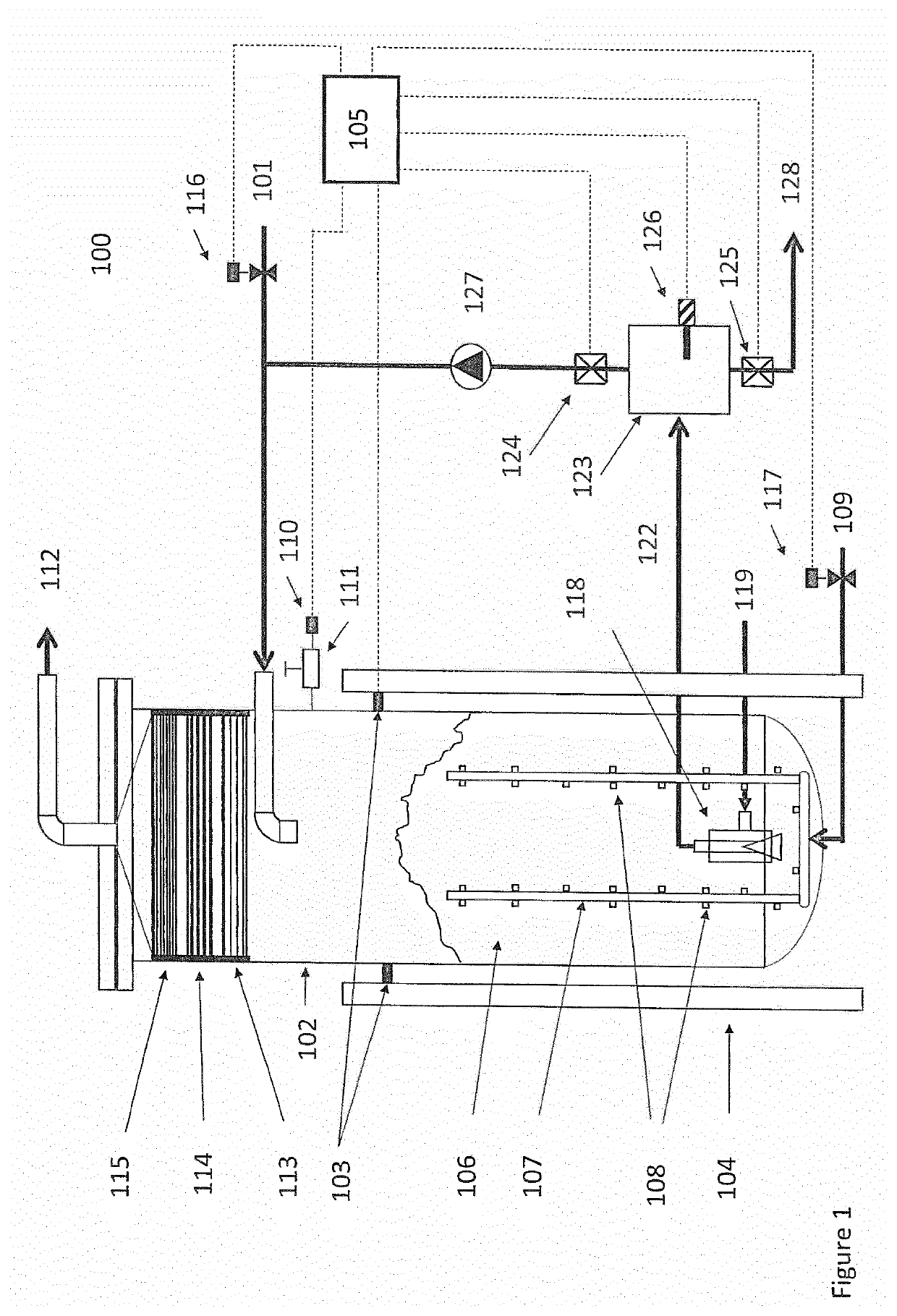
[0020]Referring to FIG. 1 there is shown a schematic of a solids particles washing system 100. The system comprises an inlet 101 that carries a sand / water mix from a de-sanding unit (not shown) into a vessel 102. The sand that enters through the inlet 101 will collect (through settlement) in the vessel to form a solids bed 106. The vessel is suspended on arms 103 within a frame 104. The arms 103 are instrumented with a weight sensor that is connected to a controller 105, which calculates the weight of sand collected in the vessel and can display this on a screen (not shown). The controller can use this information in other ways that will be described later. Within the vessel there exists piping 107 that has a plurality of nozzles, two of which nozzles are labelled 108 in FIG. 1. Those skilled in art will appreciate that the number of pipes and nozzles thereon can be adjusted to suit a particular configuration depending on, for example, the vessel size and volume of sand to be proces...


PUM


Abstract

An apparatus for washing solid particles removed from a hydrocarbon-containing fluid produced from an oil and gas production facility using a company automated unit. The apparatus comprises an inlet that carries a mixture of solids particles and water flushed from a de-sander.

Description

FIELD OF THE INVENTION[0001]The present invention relates to an apparatus for, and a method of, washing solid particles (usually sand) collected from a hydrocarbon-containing fluid produced from an oil and / or gas production facility. In particular, this invention relates to an apparatus and method for washing solid particles from a well or group of wells using an automated apparatus that monitors the cleanliness of the particles and ensures that the washed particles meet some predefined threshold (for example, regulatory limit) so that they can be safely disposed.BACKGROUND[0002]During the production of oil and gas large amounts of solids, for example, sand or chalk can be produced. The amount and type of solids can vary from reservoir to reservoir and from well to well. It can also vary during the life of the reservoir / well. For example, as the reservoir pressure decreases during production, the stress state of the matrix rock in the reservoir changes. Such changes can result in in...

Claims


Application Information

Patent Timeline
IPC IPC(8): B08B3/04B08B3/10B08B13/00C10G1/04
CPCC10G1/047B08B3/106E21B43/35B08B13/00B08B3/04B03B9/02B01D21/0024
Inventor BRUNTVEIT, JORGENLYNGBO, KARL OLE
Owner FOURPHASE
Learn More