Liquid injected propane fuel system

Pending Publication Date: 2020-10-15
AUTO GAS SERVICES LLC
View PDF0 Cites 0 Cited by
  • Summary
  • Abstract
  • Description
  • Claims
  • Application Information

AI Technical Summary

Benefits of technology

The patent describes a system for delivering liquid propane fuel to an engine. The system includes a fuel tank, a pump, and fuel rails. The fuel rails have fuel injector cavities that are connected to the pump through supply and return lines. The system also includes a vortex path that helps to remove vapor fuel from the fuel injector cavities. The technical effects of the system include reducing emissions, improving engine starting, and improving fuel efficiency.

Problems solved by technology

The vapor delivery systems of the prior art lack the fuel flow requirements needed for large displacement internal combustion engines, resulting in a lack of performance and economy.
However, the liquid delivery systems of the prior art have experienced issues with the fact that liquid propane boils or evaporates liquid propane at a low temperature at normal pressure (for example propane begins to boil at sea level at −44° F.).
Thus, the liquid delivery systems of the prior art have experienced evaporation loss (EVAP emissions) of the liquid propane, due to the inherent properties of propane, prior to disbursement of the propane into the combustion chamber(s) of an engine.
However, application of a cooling system requires the combination of both the fuel delivery system and a separate cooling system.
The combination of two separate systems provides for the increased possibility of system failure and, thus, EVAP emissions.
However, the prior art propane fuel delivery systems do not teach distribution of at least one of a proportional injection system and a direct injection system through a singular distribution assembly wherein the distribution assembly is equipped to monitor the temperature and / or pressure of the fuel advancing through the distribution assembly.
However, the prior art systems as disclosed require a delayed purging of the system upon turning on the engine system via the ignition switch.
The purging of the EVAP emissions through the fuel system, including the fuel rails, results in a delayed ignition time.
The continual delay in starting the vehicle between delivery stops subsequently causes and then increases delays between deliveries.
Thus, the prior art systems do not teach advancement of liquid propane fuel and EVAP emissions of propane through the propane delivery system in order to reduce the start time of the engine upon ignition.
However, the prior art propane delivery systems do not teach a fuel pump which is accessible for maintenance without removing the fuel from the tank.
The need to remove the fuel from the tank, increases maintenance time on the vehicle.
It is observed prior art propane vehicles experience turn around maintenance time issues at present due to the required removal of the fuel tank for servicing.

Method used


Image

  • Liquid injected propane fuel system
  • Liquid injected propane fuel system
  • Liquid injected propane fuel system

Examples


Embodiment Construction

[0061]Although the disclosure hereof is detailed and exact to enable those skilled in the art to practice the invention, the physical embodiments herein disclosed merely exemplify the invention which may be embodied in other specific structures. While the preferred embodiment has been described, the details may be changed without departing from the invention, which is defined by the claims.

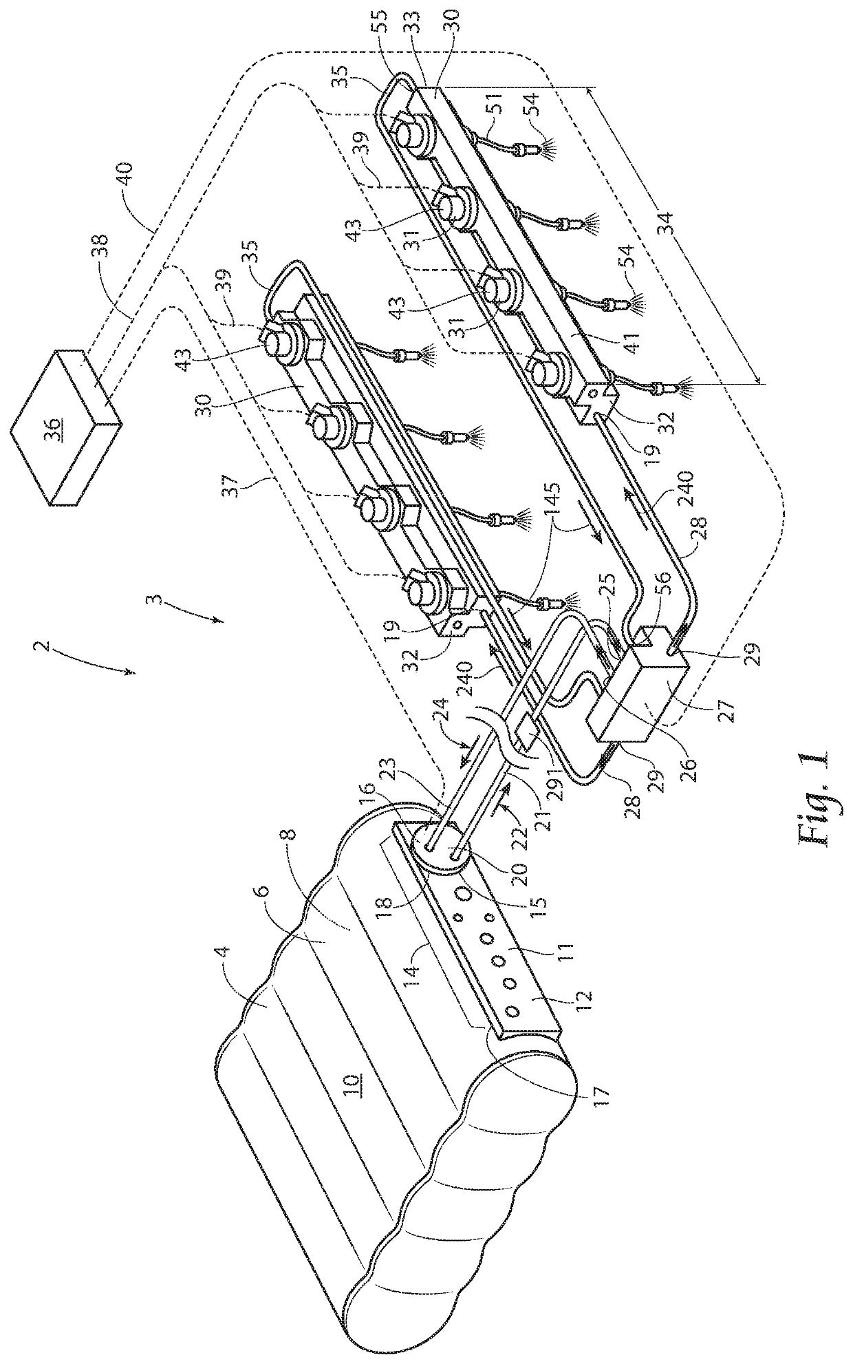
[0062]With attention to FIG. 1, a fuel system first embodiment 2 of the invention comprising a port fuel liquid propane injection system 3 is described. The fuel system first embodiment 2 comprises a fuel tank 4, a base tank valve adaptor (BTVA) assembly 16, a distribution block 27, at least on fuel rail 30, and an electronic control unit (ECU) 36 in communication for the controlled distribution of fuel to an engine assembly (not illustrated in the figure). 6. The fuel tank shell 6 defines an internal cavity 8 of the fuel tank 4, wherein the internal cavity 8 provides for storage of fuel (115, 124...


PUM


Abstract

A system according to the present invention provides for a liquid injected propane fuel system for internal combustion engines which provides for a fuel pump assembly, a base tank valve adaptor, a distribution assembly, and rail assemblies; a first embodiment of the liquid injected propane fuel system may provide for proportional fuel injection, a second embodiment may provide for direct fuel injection providing for at least substantial reduction in evaporation (EVAP) emissions, is disclosed, a third embodiment of the liquid injected propane fuel system may provide for a combination of proportional fuel injection and direct fuel injection; the invention comprising at least one of a fuel tank, an external fuel tank, a distribution block, a fuel rail and a ECU.

Description

BACKGROUND OF THE INVENTION[0001]The present invention is directed to internal combustion engines. More specifically the present invention is directed to a liquid injected propane fuel systems for internal combustion engines. More specifically the present invention is directed to a liquid injected propane fuel systems for internal combustion engines which provides for a fuel pump assembly, a base tank valve adaptor, a distribution assembly, and rail assemblies.[0002]Propane fuel in liquid form (LP) is a widely used alternative to gasoline with nearly 200,000 on-road propane vehicles with certified systems in the United States, according to the Propane Education & Research Council and provided by the U.S. Department of Energy, Alternative Fuels Data Center. The propane industry started in 1910 with the discoveries by Dr. Walter O. Snelling investigation of vapors coming from the fuel tank of a newly purchased Ford Model T. The first propane vehicle ran in 1913.[0003]Prior art propane...

Claims


Application Information

Patent Timeline
IPC IPC(8): F02M21/02
CPCF02M21/0287F02M21/0257F02M21/0245F02M21/0281F02M21/0212Y02T10/30
Inventor OMUNDSON, JOHN PATRICKWEGNER, CARL D.
Owner AUTO GAS SERVICES LLC
Why Eureka
Try Eureka