
Generator device of electrical energy with permanent magnets, particularly for the supply of electrical loads and/or batteries of vehicles

a generator device and permanent magnet technology, which is applied in the direction of motor starters, magnetic circuit rotating parts, magnetic circuit shapes/forms/construction, etc., can solve the problems of low energy output and efficiency, related energy dissipation, and the overall dimension and in particular the dimensions of stator elements

Active Publication Date: 2020-10-15
DUCATI ENERGIA
View PDF0 Cites 0 Cited by
  • Summary
  • Abstract
  • Description
  • Claims
  • Application Information

AI Technical Summary

Benefits of technology

The invention provides a generator device that uses permanent magnets to create electrical energy for vehicles. This device has the ability to produce high amounts of energy and is highly efficient, reducing the amount of fuel consumed by the vehicle. Additionally, the device is simple and cost-effective to use.

Problems solved by technology

The electrical generator and motor generator devices of known type have their main drawback tied to low performance in terms of energy output and efficiency.
Another drawback is related to the dimensions and overall dimensions of the generators and motor generators of known type and to the related dissipations of energy due to the Joule effect caused by stator windings of considerable size to obtain the desired magnetic induction values at the stator element.
Yet another drawback is tied to the overall dimensions and in particular the dimensions of the stator element in cases of application on engines with small and medium displacement.

Method used


Image

  • Generator device of electrical energy with permanent magnets, particularly for the supply of electrical loads and/or batteries of vehicles
  • Generator device of electrical energy with permanent magnets, particularly for the supply of electrical loads and/or batteries of vehicles
  • Generator device of electrical energy with permanent magnets, particularly for the supply of electrical loads and/or batteries of vehicles

Examples


first embodiment

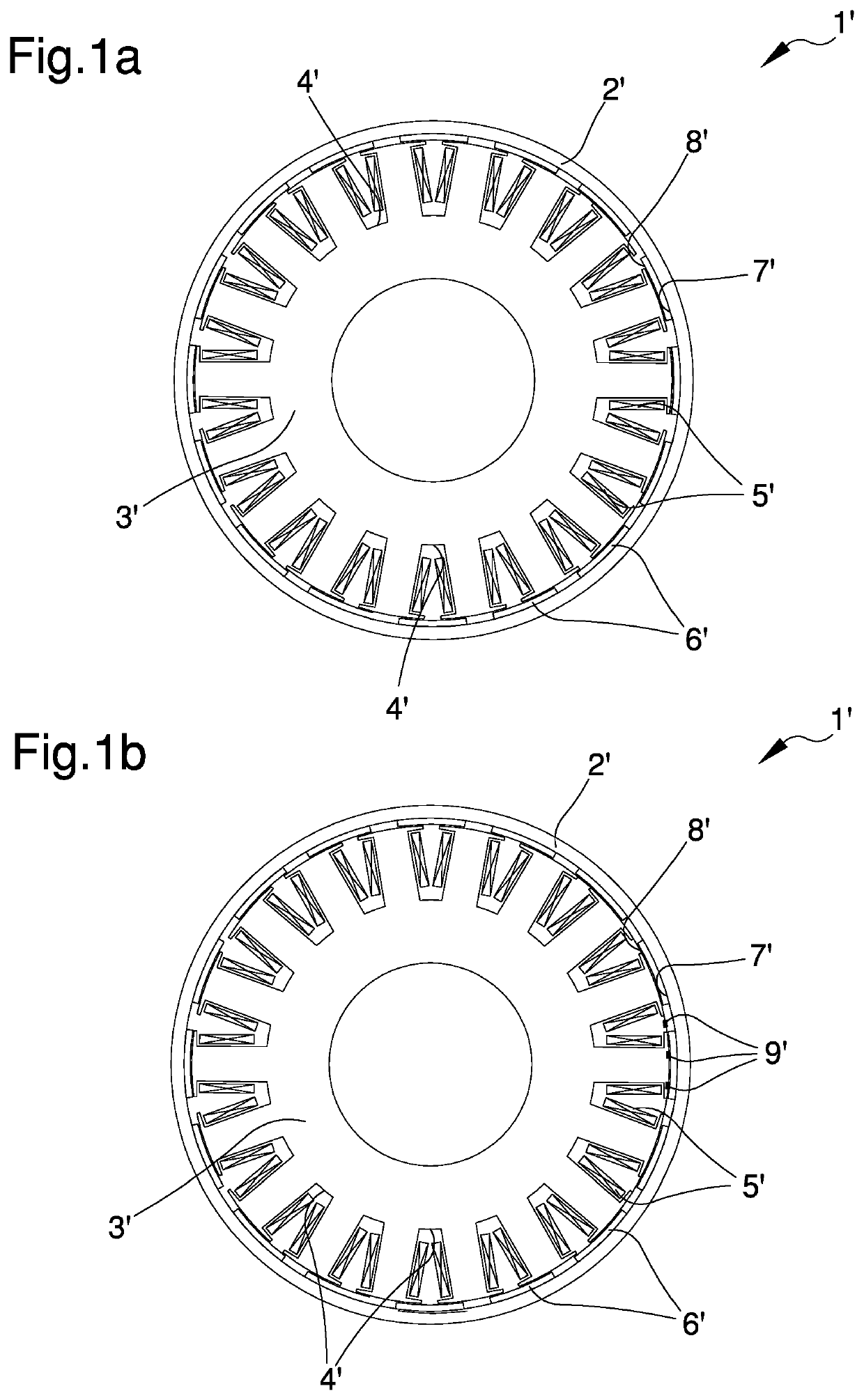
[0027]FIG. 1a is a sectional view of a device of known type in a first embodiment;

second embodiment

[0028]FIG. 1b is a sectional view of a device of known type in a second embodiment;

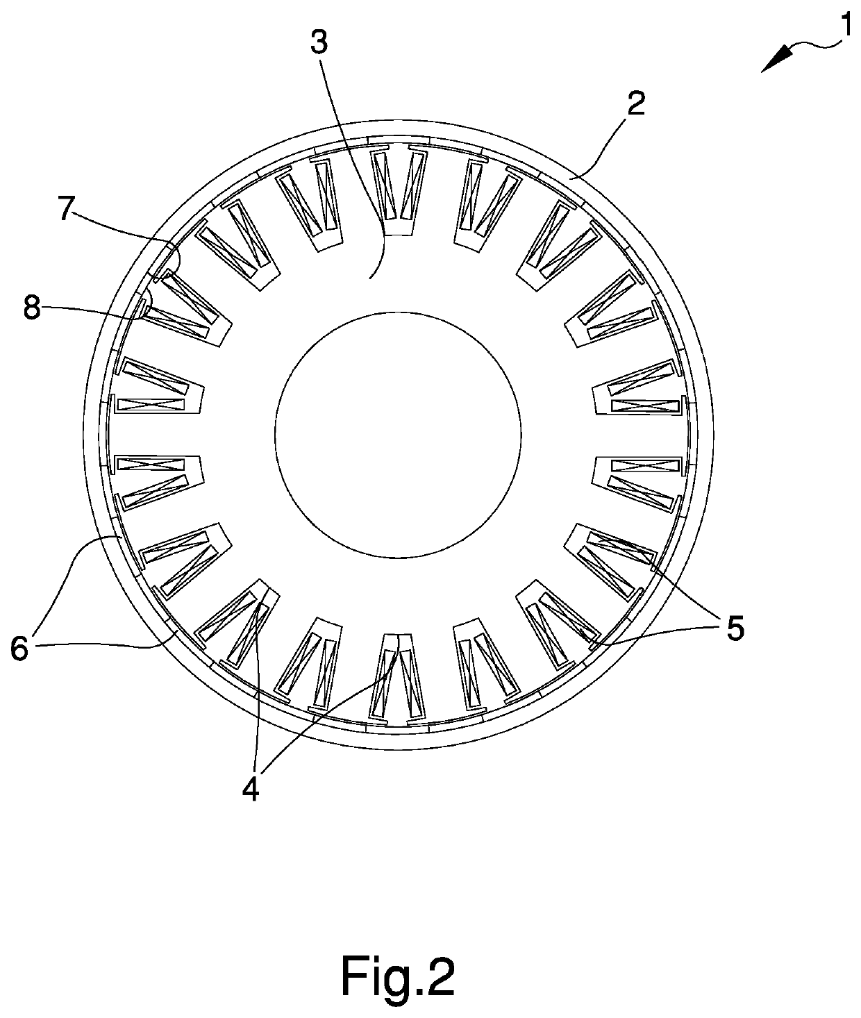
[0029]FIG. 2 is a sectional view of the device according to the invention in a first embodiment;

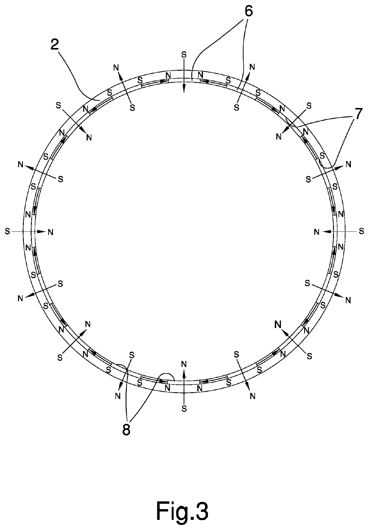
[0030]FIG. 3 is a schematic representation of a detail of the device according to the invention;

[0031]FIG. 4a illustrates the radiation diagram of the magnetic field flow of the device according to the invention;

[0032]FIG. 4b illustrates the radiation diagram of the magnetic field flow of a device of known type;

[0033]FIG. 5 graphically illustrates the pattern of the magnetic induction quantity Bz according to the distance x;

[0034]FIG. 6 is a sectional view of the device according to the invention in a second embodiment;

[0035]FIG. 7 illustrates a comparative graph between the performance obtained by a device of known type, in which the permanent magnets are arranged in a classic configuration, and by the device according to the invention, in which the permanent magnets are arranged in the Halbach configurati...


PUM


Abstract

The generator device of electrical energy with permanent magnets, particularly for the supply of electrical loads and / or batteries of vehicles, connectable to at least a driving shaft of a motor, comprises: a rotor element rotating around an axis of rotation; a stator element contained inside the rotor element, or containing the rotor element, and coaxial to the rotor element, the stator element having a plurality of stator slots; a plurality of stator windings of a conductive material arranged at each of the stator slots and connected to a power supply line; a plurality of permanent magnets having a first side associated with the rotor element and a second side facing the stator element; wherein the permanent magnets are associated with the rotor element in a configuration of the Halbach array type to define a magnetic coupling to the stator windings wherein the magnetic field flow at the second side of each of the permanent magnets is substantially greater than the flow of the magnetic field at the first side of each of the permanent magnets.

Description

TECHNICAL FIELD[0001]The present invention relates to a generator device of electrical energy with permanent magnets, particularly for the supply of electrical loads and / or batteries of vehicles.BACKGROUND ART[0002]In the particular sector of devices for the supply of two or four-wheel motor vehicles with small or medium displacement for supplying on-board electrical loads and / or for recharging the battery, the use is known of electrical machines, of the type of permanent magnets generators, directly positioned on the driving shaft of a motor.[0003]In particular, the use of permanent magnets, made of rare earths, permits obtaining compact and high performance generators particularly suited for all those applications where overall dimensions, weight and performance are the most important restraints for motor vehicle performance.[0004]In some motorcycle applications, especially in the case of small-displacement motorcycles including, e.g., single cylinder 100 cm3 engines, the power ge...

Claims


Application Information

Patent Timeline
Patent Type & Authority Applications(United States)
IPC IPC(8): H02K21/22H02K7/18H02K11/04H02K11/215
CPCF02N11/04H02K11/215H02K21/22H02K11/048H02K7/1815H02K1/2783H02K11/04H02K1/27
Inventor COMPRI, ANDREABERGHI, ALESSANDROREGAZZI, GIANNI
Owner DUCATI ENERGIA
Learn More