Switching-mode power supply circuit

Active Publication Date: 2020-10-15
SHANGHAI TUITUO TECH CO LTD
View PDF0 Cites 6 Cited by
  • Summary
  • Abstract
  • Description
  • Claims
  • Application Information

AI Technical Summary

Benefits of technology

[0028]The SMPS circuit provided by the present invention comprises two input rectification loops for outputting voltages to storage capacitor and boost capacitor, respectively. The storage capacitor and the boost capacitor are connected at terminals of the same voltage polarity. The storage capacitor also serves as an output capacitor of the boost circuit. The SMPS circuit further comprises DC-DC converter and first switching component connected between the storage capacitor (positive terminal) and the positive input terminal of the DC-DC converter (primary winding of transformer, buck-boost inductor or Zeta inductor, etc.). Boost inductor and boost capacitor are connected in series and then parallelly connected to the first switching component. One terminal of the boost capacitor is connected to a positive terminal of the storage capacitor, and the other terminal is connected to two poles (L and N) of AC input through the second rectification circuit, or connected to negative pole of DC input. The feedback control circuit controls the turn-on (conduct) and turn-off (cut off) of the first switching component to realize the conversion output of the SMPS circuit, and to realize simultaneous operation of the boost circuit and the DC-DC converter (flyback, buck-boost, forward, push-pull, Zeta, etc.) topology to boost and convert input voltage and to achieve power factor correction for AC power supply. The SMPS circuit of the present invention adopts an active PFC circuit (boost circuit), which has a good active PFC performance. As the PWM (or PFM) control unit and the power switching component (first switching component) in the DC-DC converter (flyback,

Problems solved by technology

Resistor passive PFC is easily realized at very low cost, but has a high loss, a high temperature and a low power factor, and thus is neither suitable for high power supplies, nor suitable for Class C and Class D equipment.
Inductor passive PFC is also easily realized at low cost, but has a relatively high loss and a low power factor, and thus is also not good enough for high power supplies and class C, class D equipment.
However, the circuit is complex with more components, leading to a high cost and a large space occupancy.
The

Method used


Image

  • Switching-mode power supply circuit
  • Switching-mode power supply circuit
  • Switching-mode power supply circuit

Examples


Embodiment Construction

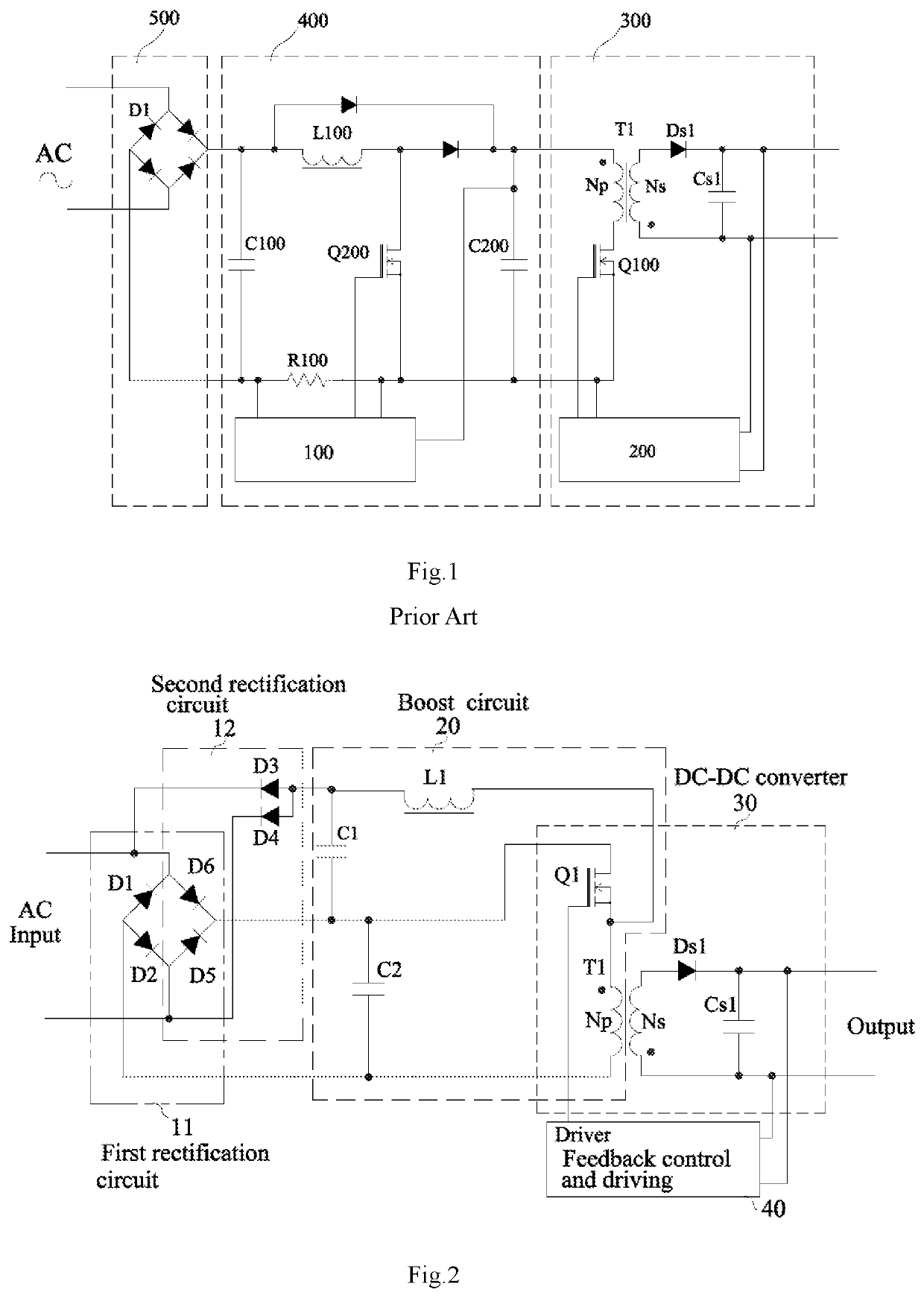
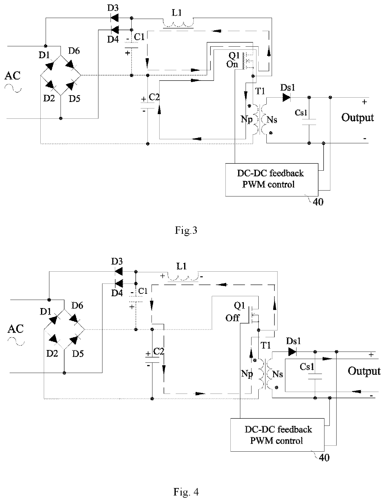
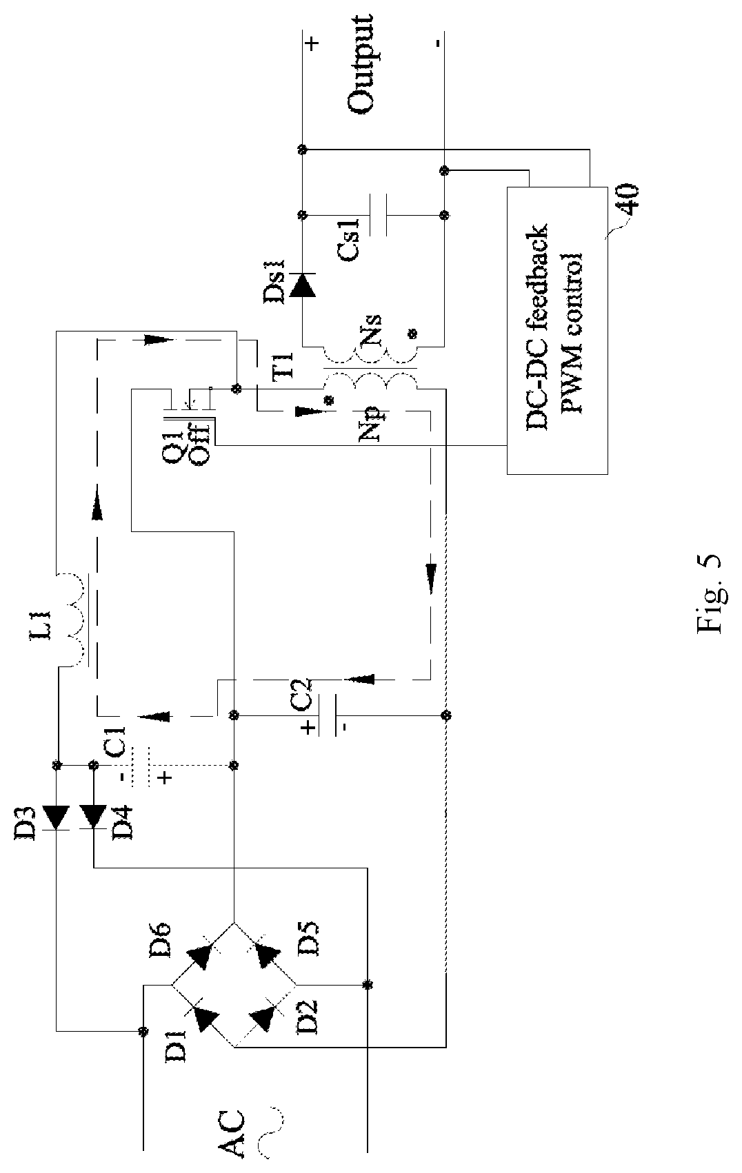
[0051]The following embodiments together with figures further describe the SMPS circuit of the present invention. According to the description and claims, advantages and features of the present invention will become more obvious. It should be noted that attached figures are not precisely proportional to the actual. They are just for the purpose of assisting the description of embodiments of the present invention in an easy and clear manner.

[0052]The core concept of the present invention is to provide a switching mode power supply circuit to solve the problem of high complexity existed with traditional boost circuits.

[0053]To achieve this, the present invention provides a switching mode power supply circuit, comprising a boost inductor, a boost capacitor, a storage capacitor, a transformer or DC-DC inductor, a first switching component, an output rectification component, a filter capacitor, a feedback and control circuit, a first rectification circuit and a second rectification circu...


PUM


Abstract

A switching-mode power supply circuit includes a boost inductor, a boost capacitor, a storage capacitor, a transformer or DC-DC inductor, a first switching component, an output rectification component, a filter capacitor, a feedback and control circuit, first and second rectification circuits. When first switching component conducts, the boost inductor, boost capacitor and first switching component form a first boost loop, the boost inductor stores energy, and the storage capacitor, first switching component and transformer or DC-DC inductor form a first DC-DC loop. When first switching component cuts off, the boost inductor, boost capacitor, storage capacitor and transformer or DC-DC inductor form a second boost loop, and the transformer or DC-DC inductor, output rectification component and filter capacitor form a second DC-DC loop. The filter capacitor supplies energy to a load. The feedback and control circuit drives the first switching component to turn on/off according to a chopping wave having specific frequency and duty to control a voltage, current or power output to the load.

Description

CROSS-REFERENCE TO RELATED APPLICATION[0001]This application is Continuation of International Patent Application No. PCT / CN2019 / 083637, filed on Apr. 22, 2019, entitled “SWITCHING-MODE POWER SUPPLY CIRCUIT” which claims priority of Chinese Patent Application No. 201810371989.5, filed on Apr. 24, 2018, and the entire disclosures of which are incorporated herein.TECHNICAL FIELD[0002]The present invention relates to the technical field of power electronics, and in particular, relates to a switching mode power supply circuit.BACKGROUND[0003]A switching mode power supply circuit formed by a combination of boost circuit with single ended and double ended DC-DC converter (flyback, forward, buck-boost, push-pull, ZETA or SEPIC) is able to realize voltage boosting and output converting, and also the function of AC power factor correction.[0004]An AC-DC power supply of an electrical equipment that connects to AC power grid line has to satisfy mandatory requirements on current harmonics accord...

Claims


Application Information

Patent Timeline
IPC IPC(8): H02M1/42H02M3/158H02M3/335H02M3/337H02M1/08
CPCH02M3/3376H02M3/1582H02M2003/1557H02M3/33523H02M1/08H02M1/4225H02M3/156H02M3/33569Y02B70/10H02M3/33507H02M1/4258H02M1/0048H02M3/1557
Inventor LI, RENHONGSHEN, ZHUO
Owner SHANGHAI TUITUO TECH CO LTD
Why Eureka
Try Eureka