
Systems, apparatuses, and methods for reducing the size of a material

a technology of system and material, applied in the direction of soldering apparatus, manufacturing tools,auxillary welding devices, etc., can solve the problems of laborious and reduced yield, and achieve the effect of reducing length

Active Publication Date: 2020-11-05
ROZOT THIERRY
View PDF0 Cites 1 Cited by
  • Summary
  • Abstract
  • Description
  • Claims
  • Application Information

AI Technical Summary

Benefits of technology

The present invention is about an automated system and method for making cuts in large materials like steel slabs. The system includes a cutting apparatus with a torch arm and a support for the material, as well as a deburring means for removing any burrs that might occur during the cutting process. The technical effect of this invention is that it can simultaneously perform both cutting and deburring, reducing the labor and process time required for these tasks.

Problems solved by technology

Such defects may be the result of metallurgical defects or irregularities often present at the ends of a slab, as well as burrs created when the slab is cut to a length suitable for producing a plate.
If a rolling operation produces plates containing defects resulting from defects or burrs present in the slabs from which they were rolled, plates must be produced that are larger than otherwise required to permit removal of the defects, with the result that yield is reduced.
Deburring is often performed with a slash hammer or grinding machine and is therefore very labor intensive.

Method used


Image

  • Systems, apparatuses, and methods for reducing the size of a material
  • Systems, apparatuses, and methods for reducing the size of a material
  • Systems, apparatuses, and methods for reducing the size of a material

Examples


Embodiment Construction

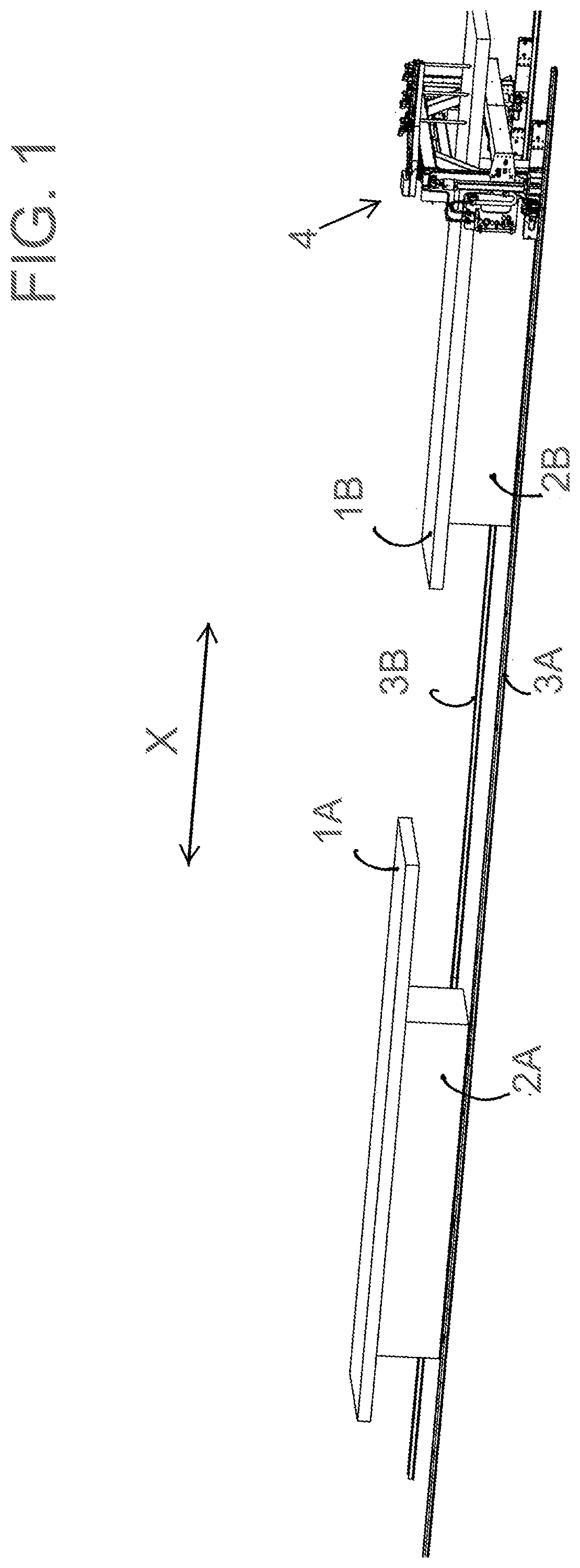
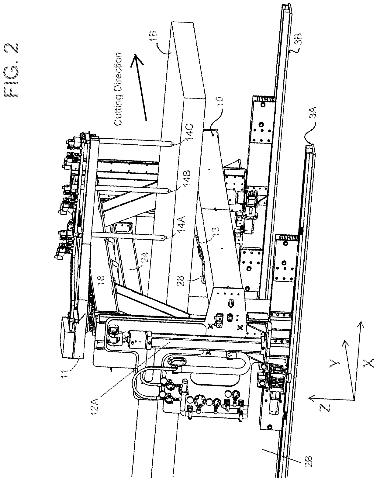
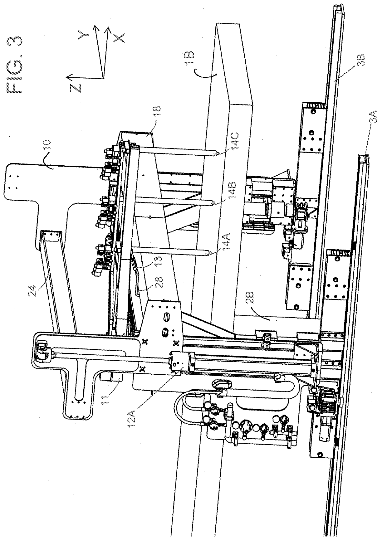
[0016]FIGS. 1 through 8, 9 through 12, and 13 through 17 schematically represent nonlimiting embodiments of automated cutting systems adapted to make at least lateral / cross (Y-direction / axis) cuts in large masses of material, for example, to reduce the size (length) of a metal slab by making through-thickness (Z-direction / axis) cuts in the slab. Preferably, the systems also provide the capability of reducing if not eliminating the need to perform separate and subsequent deburring operations on a slab after undergoing such a cut. The cutting systems are particularly well suited for performing cutting and deburring operations on steel slabs and, as a matter of convenience, will be shown and described in reference to cutting steel slabs, though it should be understood that the cutting systems are not so limited.

[0017]To facilitate the descriptions provided below of the embodiments represented in the drawings, relative terms, including but not limited to, “vertical,”“horizontal,”“latera...


PUM

PropertyMeasurementUnit
temperatureaaaaaaaaaa
temperaturesaaaaaaaaaa
sizeaaaaaaaaaa

Abstract

Automated systems and methods for making cuts in large masses of materials, including lateral cuts to reduce the lengths of steel slabs and produce therefrom slabs of desired sizes for producing steel plates. Such a system includes an apparatus having a support that supports the material, and a torch arm translatable in a Y-direction of the material and supporting a torch that emits a torch flame to make a cut in a Z-direction of the material while supported by the support. The apparatus has a deburring device associated with the torch arm and translatable in the Y-direction to perform a deburring operation by emitting an oxidizing gas stream that simultaneously removes burrs along the lateral cut produced by the torch in synchrony with translation of the torch in the Y-direction as the lateral cut is produced by the torch to oxidize the burrs before the burrs solidify.

Description

CROSS-REFERENCE TO RELATED APPLICATIONS[0001]This application claims the benefit of U.S. Provisional Application Ser. Nos. 62 / 842,559 filed May 3, 2019, 62 / 842,564 filed May 3, 2019, and 62 / 842,574 filed May 3, 2019. The contents of these prior applications are incorporated herein by reference.BACKGROUND OF THE INVENTION[0002]The invention relates to systems, apparatuses, and methods for reducing the size of a material. The invention particularly relates to automated systems and methods for making cuts in large masses of materials, including but not limited to the ability to make cuts to reduce the sizes, and particularly the lengths, of steel slabs and produce therefrom reduced-size pieces, preferably with the ability to eliminate or at least reduce the need to perform a separate deburring operation on a material after undergoing such a cut.[0003]For achieving high yields of quality steel plates in a steel mill, it is important that a slab from which a plate is rolled is free of de...

Claims


Application Information

Patent Timeline
Patent Type & Authority Applications(United States)
IPC IPC(8): B23K26/38
CPCB23K26/38B23K2103/04B23K37/0235B23K7/003B23K7/08B23K2101/18B22D11/1265B22D11/126B23K7/102B23K7/06
Inventor ROZOT, THIERRY
Owner ROZOT THIERRY
Learn More