
Cold cathode x-ray tube and control method therefor

a technology of x-ray tube and control method, which is applied in the direction of x-ray tube cathode assembly, x-ray tube gas control, x-ray tube, etc., can solve the problems of time-consuming and laborious, and achieve the effect of preventing the time-consuming and labor-intensive reduction of anode current and driving stably over a long period of tim

Inactive Publication Date: 2020-11-12
NANO X IMAGING LTD
View PDF0 Cites 0 Cited by
  • Summary
  • Abstract
  • Description
  • Claims
  • Application Information

AI Technical Summary

Benefits of technology

The present invention relates to a cold cathode X-ray tube, and aims to prevent the generation of hydrogen gas during operation. This is achieved by placing the hydrogen generation part on a portion of the anode surface other than the target surface, which allows for stable operation over a long period of time.

Problems solved by technology

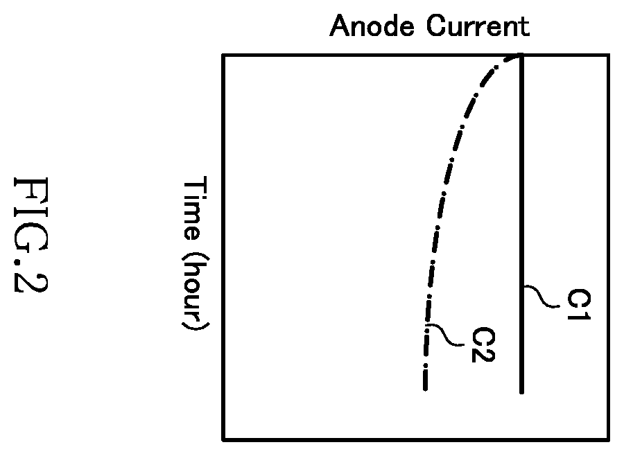
Therefore, in conventional cold cathode X-ray tubes, there may occur such a problem that a vacuum degree is lowered by gas generated during the operation of the X-ray tube to change the cathode surface conditions to cause temporal reduction in anode current.

Method used


Image

  • Cold cathode x-ray tube and control method therefor
  • Cold cathode x-ray tube and control method therefor
  • Cold cathode x-ray tube and control method therefor

Examples


Embodiment Construction

Mode for Carrying out the Invention

[0020]Preferred embodiments of the present invention will be explained below in detail with reference to the accompanying drawings.

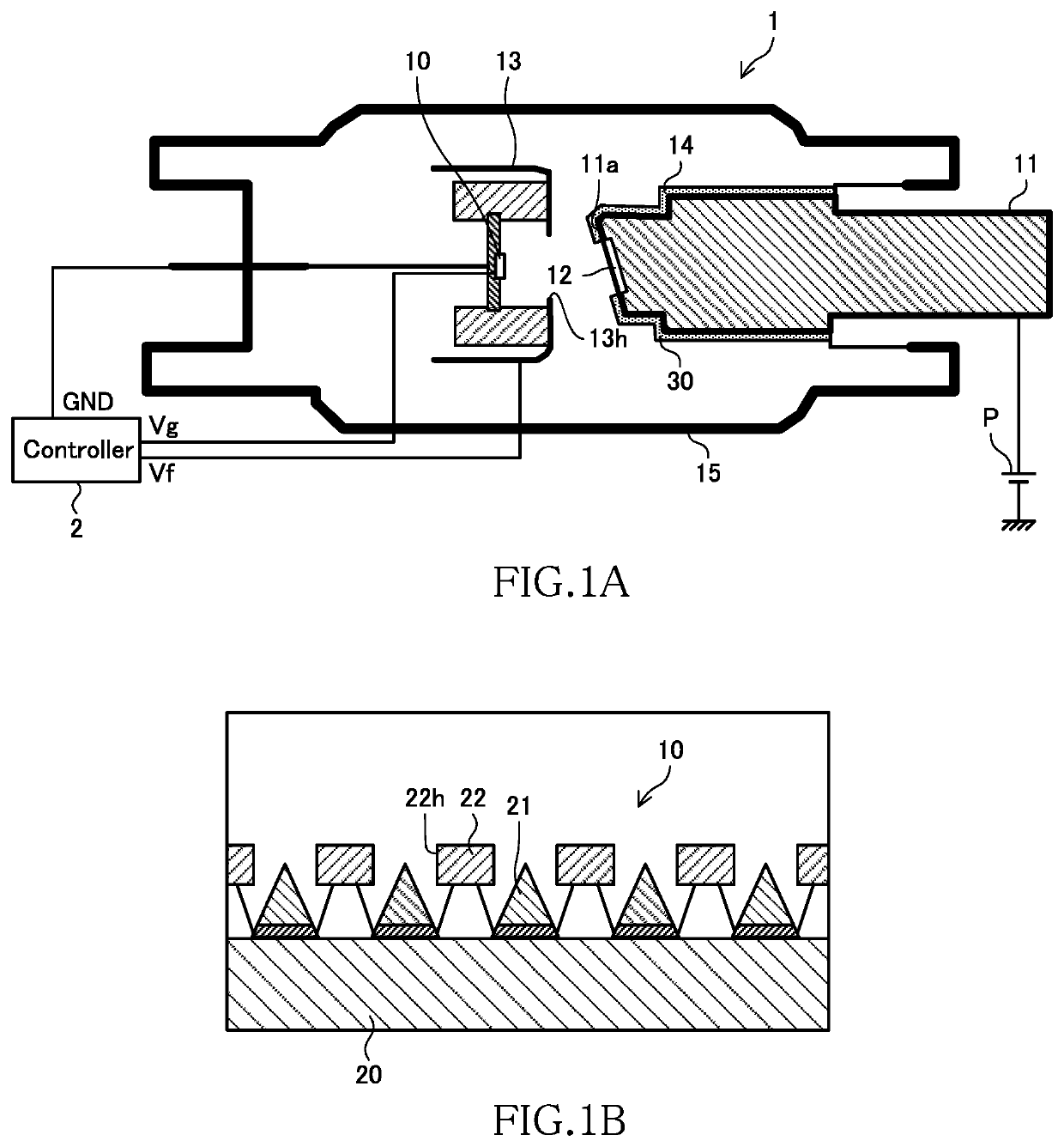
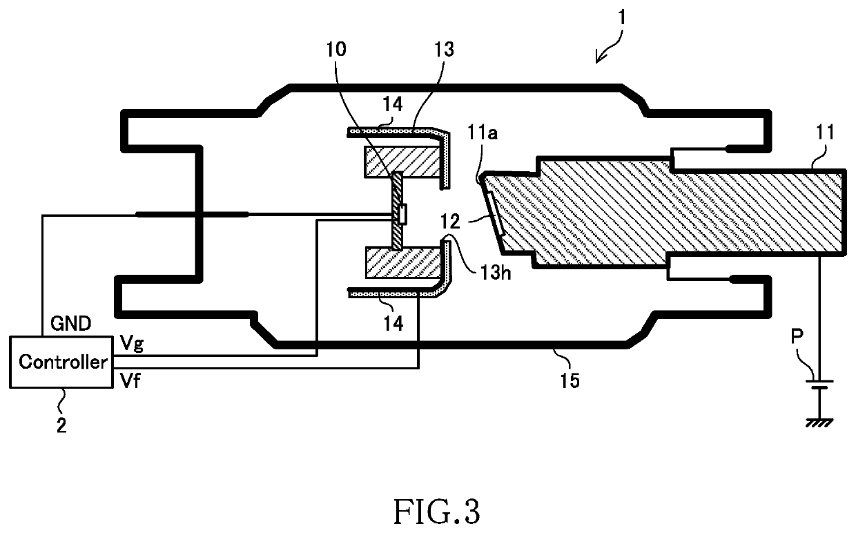
[0021]FIG. 1A is a schematic cross-sectional view of a cold cathode X-ray tube 1 according to an embodiment of the present invention. As illustrated, the X-ray tube 1 has a structure in which an electron emission part 10, an anode part 11, a target 12, a focus structure 13, and a hydrogen generation part 14 are disposed inside a housing 15. FIG. 1 also illustrates a controller 2 for the X-ray tube 1.

[0022]The housing 15 is a sealed member made of glass, ceramic, or stainless. Although not illustrated, a valve is provided in the housing 15, and exhaust of gas from the housing 15 and injection of gas into the housing 15 are performed as needed through the valve. For example, before the cold cathode X-ray tube 1 is operated under the control of the controller 2, a vacuum pump is used to exhaust the gas from the housing 15 ...


PUM


Abstract

The object of the present invention is to provide a cold cathode X-ray tube capable of being driven stably over a long period of time by preventing temporal reduction in anode current. A cold cathode X-ray tube 1 comprises an electron emission part 10 including an electron emission element using a cold cathode, an anode part 11 disposed opposite to the electron emission part 10, a target 12 disposed on a part of a surface of the anode part 11, a housing 15 in which the electron emission part 10, the anode part 11, and the target 12 are disposed, and a hydrogen generation part 14 that is made of a material that generates hydrogen when receiving collision of electrons and disposed on a portion other than the surface of the target 12 out of surfaces existing in the housing 15.

Description

TECHNICAL FIELD[0001]The present invention relates to a cold cathode X-ray tube and a control method therefor.BACKGROUND ART[0002]Conventional X-ray tubes use a filament as an electron emission element and use thermoelectrons emitted from the filament as an electron source. On the other hand, there are recently proposed some X-ray tubes (cold cathode X-ray tubes) that use a cold cathode as an electron emission element (e.g., U.S. Pat. No. 7,778,391, U.S. Pat. No. 7,809,114, and U.S. Pat. No. 7,826,595).[0003]As compared to the X-ray tubes that use a filament as an electron emission element, the cold cathode X-ray tubes have a property that the electron emission amount thereof is subject to cathode surface conditions. Therefore, in conventional cold cathode X-ray tubes, there may occur such a problem that a vacuum degree is lowered by gas generated during the operation of the X-ray tube to change the cathode surface conditions to cause temporal reduction in anode current. In order to...

Claims


Application Information

Patent Timeline
IPC IPC(8): H01J35/06H01J35/20H01J35/16
CPCH01J35/065H01J35/16H01J35/20H01J2235/20H01J2235/062
Inventor HIDENORI, KENMOTSU
Owner NANO X IMAGING LTD
Learn More