Battery life time based on sensor data

Active Publication Date: 2020-11-19
SCHNEIDER ELECTRIC IND SAS
View PDF0 Cites 2 Cited by
  • Summary
  • Abstract
  • Description
  • Claims
  • Application Information

AI Technical Summary

Benefits of technology

[0048]This enables to store more power in battery. The counterpart is that it limits the life cycle of the battery, which is however compensated by the above technical features of the invention. Therefore, a minimum autonomy (40 days for example) during a minimum l

Problems solved by technology

However, the number of charge cycles of a battery is limited and depends on the battery technology (traditional or solid-state batteries for example), on the depth of dischar

Method used


Image

  • Battery life time based on sensor data
  • Battery life time based on sensor data
  • Battery life time based on sensor data

Examples


Example

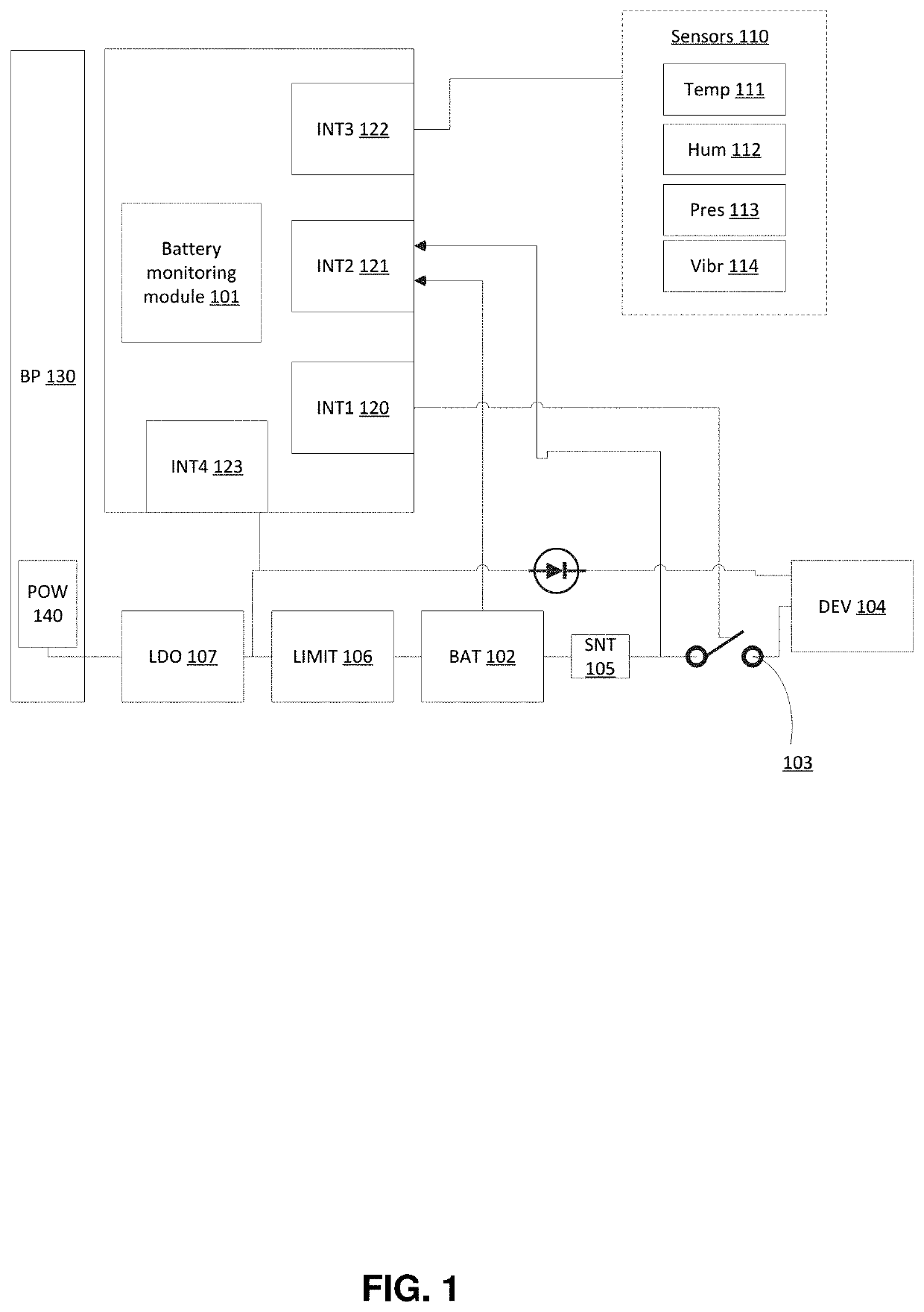
[0061]Referring to FIG. 1, there is shown a system according to some embodiments of the invention.

[0062]The system comprises a device 104, in particular a power retention device in the context of the invention, alternatively powered by a battery 102 or by a power source 140. In what follows, the device 104 is considered as being a Real Time Clock, RTC. However, no restriction is attached to the device 104 which can be any device requiring power retention, such as a memory or a low power, LP, Remote Terminal Unit, RTU or any device that has a function that requires to be permanently powered. As it can be powered by the battery 102, the device 104 may be called “load of the battery” hereafter.

[0063]The RTC 104 may be integrated to a larger entity, other modules of the larger entity being synchronized based on the RTC signal for example.

[0064]The power source 140 may be an external supply or may be the general power supply of the larger entity. The RTC 104 may be connected to the power...


PUM


Abstract

The invention relates to a system for controlling supply of a device (104). The device can be a power retention device that requires to be permanently powered. To this end, it can be alternatively powered by a power supply (140), in a first mode, or by a battery (102), in a second mode. At least one sensor (110-114; 105) of the system acquires data related to the battery, such as environmental data, the voltage of the battery or the discharge current of the battery. Based on the data and at least one characteristic curve of the battery, a battery monitoring module is configured to switch between the first and second modes to improve the lifetime of the battery.

Description

BACKGROUND[0001]The present invention relates to monitoring of a battery life cycle, in particular, while not exclusively, in the context of solid-state batteries.[0002]Batteries or supercapacitors are generally used to provide power to devices when it is not powered by another power source. In particular, power retention devices such as Real Time Clocks, RTC, require to be continually powered, even in case of power supply outage. To this end, traditional back-up systems integrate supercapacitors or chemical batteries to provide power in any situation. For example, when the output voltage of the power source drops below a threshold value, the back-up battery can be used to power the data retention device.[0003]The wording “power retention device” designates any device that embeds a critical function that should not be interrupted, even when the power source is turned off or is defective, such as a memory or an RTC for example.[0004]RTCs are used in many applications, and in particul...

Claims


Application Information

Patent Timeline
IPC IPC(8): G01R31/3842G01R31/36H02J7/00H03K17/00G01R31/392
CPCG01R31/392G01R31/3648H02J7/005H03K17/005G01R31/3842H02J9/068G01R31/382H02J7/0068H02J9/061G01R19/16542
Inventor BIEHLER, AYMERICFERRY, DIDIERRUDELOU, GHISLAIN
Owner SCHNEIDER ELECTRIC IND SAS
Why Eureka
Try Eureka