Observation Instrument and a Video Imager Arrangement Therefor

a video imager and optical arrangement technology, applied in the field of observation instruments, can solve the problems of limited shaft diameter and strict space limitation of the electronic image sensor of the imaging unit, and achieve the effect of compact and robust optical arrangement, compact and robust, and unchanged image quality

Active Publication Date: 2020-11-19
KARL STORZ GMBH & CO KG
View PDF0 Cites 4 Cited by
  • Summary
  • Abstract
  • Description
  • Claims
  • Application Information

AI Technical Summary

Benefits of technology

[0023]According to a preferred embodiment of the invention, the optical deflection element is a deflection prism that is arranged on the image pick-up surface of the image sensor and fixed to the image sensor, preferably rigidly fixed to the image sensor. In particular, the deflection prism has an entrance face, a deflection face and an exit face, the deflection face being at an angle of 45° to each of the entrance and exit faces, thus achieving a deflection angle of 90°. The deflection prism is preferably arranged having its exit face adjacent to the image pick-up surface of the image sensor. The exit face, in particular, has a size not less than a size of the image to be transmitted to the image pick-up surface of the image sensor, and preferably a length of the exit face, as measured parallel to the optical axis, exceeds the diameter of an image circle by not more than about 50%. The deflection prism may be glued with its exit face on the light-sensitive surface or on a cover glass of the light-sensitive surface of the image sensor. Further, a filter may be placed between the image pick-up surface and the exit face of the deflection prism. In this way, a compact and robust optical arrangement can be provided.
[0024]Preferably, the imaging unit comprises a sleeve holding the objective lens system, and the deflection element is a deflection prism fixed to an image end of the sleeve. In particular, the sleeve may have a tubular shape, lenses and other optical elements of the objective lens system being mounted inside the tubular sleeve. The deflection prism may be fixed rigidly to the sleeve, for example by mounting the sleeve to an entrance face of the deflection prism, or by mounting the deflection prism and the sleeve to a common frame or housing. According to a particularly preferred embodiment, the entrance face of the deflection prism is fixedly held adjacent to an image or proximal end of the sleeve, and the exit face is fixed to the image pick-up surface of the image sensor. Such an optical arrangement is particularly compact and robust, providing unchanged image quality independent of tilting angle.
[0025]Most preferably, the optical axis of the objective lens system is offset to a sensor plane of the electronic image sensor. The offset may depend on the dimensions of the objective lens system and of the deflection prism, which in turn may be related to the dimensions of the image generated on the image pick-up surface. For example, the offset may be about a diameter of the objective lens system, possibly including the sleeve. In this way a particularly simple optical design can be achieved, reducing production cost and optical losses.
[0026]According to a preferred embodiment, the pivot axis is arranged at a distal edge or in a distal end section of the electronic image sensor. Generally, electronic image sensors have an approximately rectangular shape having a shorter side and a longer side. Due to packaging and mechanical and electrical connections, the image sensor exceeds the size of the light-sensitive surface. In the present case, the image sensor may be arranged such that its shorter sides are approximately transverse to the longitudinal axis of the distal end section of the shaft. In a pivoting position in which the sensor plane is parallel to the longitudinal axis of the distal end section of the shaft, that one of the two edges forming the shorter sides of the image sensor that is closer to the distal end of the shaft is denoted the distal edge of the image sensor. In accordance with the present embodiment, the axis about which the imaging unit can be pivoted is located along or near the distal edge of the image sensor. The pivot axis may be defined mechanically by pivot points on opposing sides of a frame or housing of the imaging unit, interacting with corresponding bearings on an inner side of the shaft or in an inner structure of the shaft. Depending on the dimensions of the image sensor and the objective lens system, as well as depending on the available space in the distal end section of the shaft, an advantageous range of viewing directions can be achieved in this way.

Problems solved by technology

In prior art variable-direction-of-view video endoscopes having a pivotable imaging unit, the size of the electronic image sensor of the imaging unit is strictly limited by the available space inside the distal end section of the endoscope shaft.
On the other hand, the shaft diameter is limited by the application for which the endoscope is to be employed, for example by the diameter of a natural access to an internal body cavity.

Method used


Image

  • Observation Instrument and a Video Imager Arrangement Therefor
  • Observation Instrument and a Video Imager Arrangement Therefor
  • Observation Instrument and a Video Imager Arrangement Therefor

Examples


first embodiment

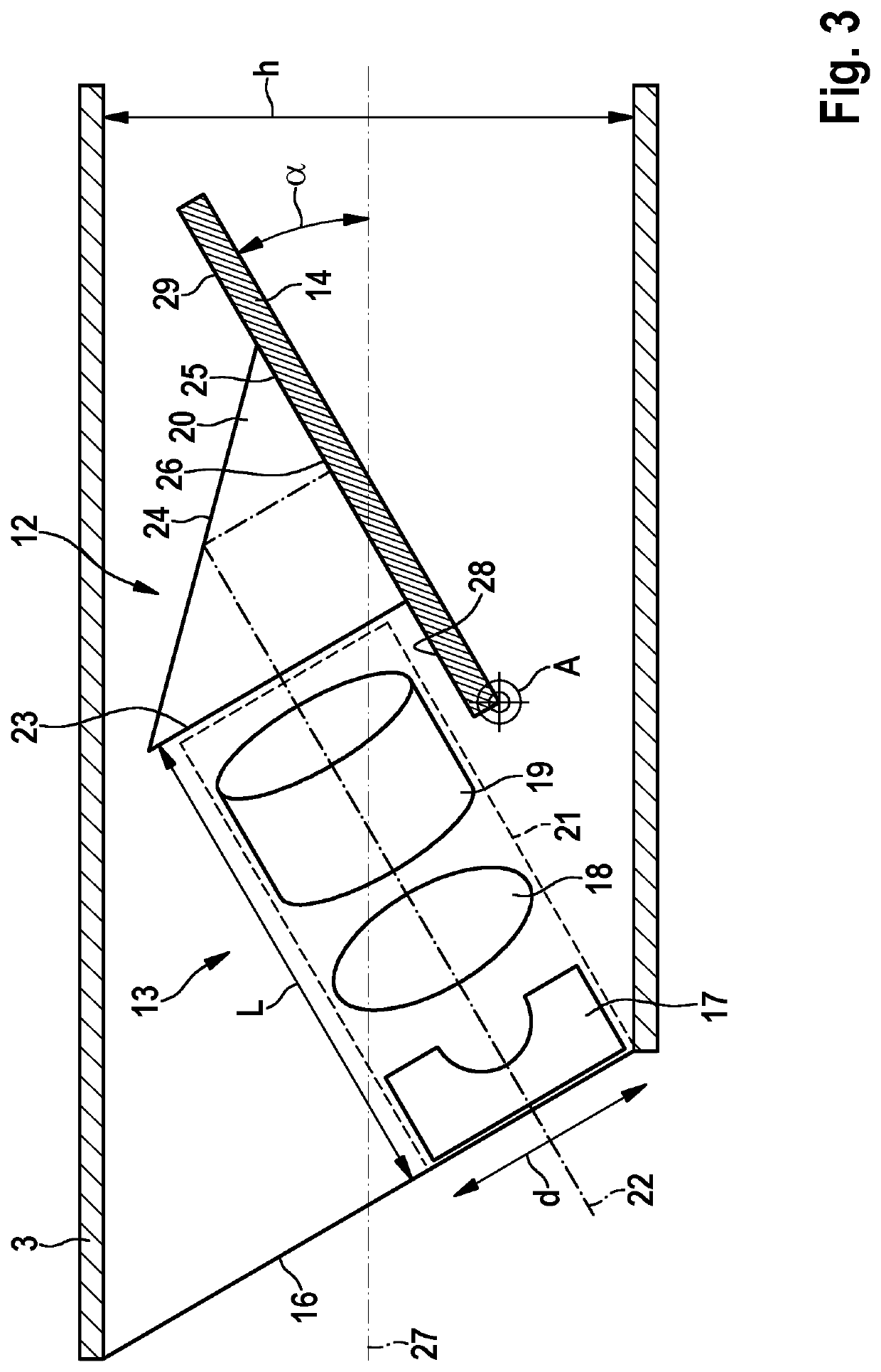
[0048]The imager arrangement according to the present invention is shown in a schematic sectional view in FIG. 3. The imaging unit 12 is configured as shown in FIG. 2c and described above, while FIG. 3 shows further details. As indicated by dashed lines, the lens 17 and the further optical elements 18, 19 of the objective lens system are held in their respective positions by a sleeve 21 which is fixedly connected to the deflection prism 20 and the image sensor 14. The lens 17, the optical elements 18, 19, and the deflection prism 20 are configured such that rays entering the imaging unit 12 from an object field along or close to an optical axis 22, pass through the lens 17 and the optical elements 18, 19, enter into the deflection prism 20 at a right angle to an entrance face 23, are deflected by 90° at the deflection face 24 and exit from the deflection prism 20 at a right angle to an exit face 25. The deflection prism 20 is held on the image sensor 14 such that the exit face 25 is...

third embodiment

[0055]In a variation of the embodiment of FIGS. 6a and 6b and as depicted in FIGS. 7a and 7b, the tube 3 or at least the central compartment 9″ may be sealed by a curved cover glass 30. The cover glass 30 may be curved in a circular arc about the pivot axis A, such that it is intersected perpendicularly by the optical axis 22 of the objective lens system at the end positions of the imaging unit 12 as shown in FIGS. 7a and 7b, and preferably at all possible viewing angles. The curved cover glass 30, on the other hand, may be embodied as a section of a sphere having its center of curvature on the pivot axis A, or may be curved in a shape that is not symmetrical with respect to the pivot axis A. Although a curved cover glass 30 is shown only in a variation of the third embodiment, a curved cover glass may be provided in corresponding variations of the other embodiments.

[0056]The three embodiments described differ in the maximal allowable length of the image sensor 14, which may exceed ...


PUM


Abstract

An observation instrument has a shaft and an imaging unit, the imaging unit comprising an objective lens system and an electronic image sensor arranged for picking up an image generated by the objective lens system, the imaging unit being pivotably arranged in a distal end section of the shaft, a pivot axis of the imaging unit being transverse to a longitudinal axis of the distal end section of the shaft, wherein the image sensor is arranged substantially parallel to an optical axis of the objective lens system and the imaging unit comprises a deflection element for deflecting light exiting from an image end of the objective lens system to an image pick-up surface of the image sensor. The invention also relates to a video imager arrangement for an observation instrument.

Description

CROSS REFERENCE TO RELATED APPLICATIONS[0001]This application claims priority to German Application No. 102019003378.7 filed May 14, 2019, entitled, “OBSERVATION INSTRUMENT AND VIDEO IMAGER ARRANGEMENT FOR AN OBSERVATION INSTRUMENT” and is incorporated herein by reference.FIELD OF THE INVENTION[0002]The present invention relates to an observation instrument, particularly one in the field of endoscopy, and to a distally placed video imager arrangement for such an observation instrument.BACKGROUND OF THE INVENTION[0003]Endoscopic examination techniques have prevailed in a multiplicity of medical and veterinary fields of application, as well as in many non-medical fields. In such examination techniques, an endoscope, which has an elongate shaft with an imaging optical system, is introduced into an internal cavity of a human or animal body or another object to be examined. The elongate shaft that is configured for being inserted into the cavity of the body or other object may be rigid, ...

Claims


Application Information

Patent Timeline
Patent Type & Authority Applications(United States)
IPC IPC(8): G02B23/24H04N5/225
CPCA61B1/00096A61B1/00183A61B1/051G02B23/2484H04N5/2254G02B23/243H04N2005/2255H04N23/55H04N23/555
Inventor BAUMANN, HARALDSCHWARZ, PETER
Owner KARL STORZ GMBH & CO KG
Why Eureka
Try Eureka