Electric device

a technology of electric devices and contact parts, applied in the direction of coupling contact parts, coupling device connections, material of connection contact parts, etc., can solve the problems of increasing distances and enlarge the occupation space of switch devices, so as to reduce the current density, and reduce the amount of material.

Active Publication Date: 2020-11-19
ZHU GONG
View PDF0 Cites 0 Cited by
  • Summary
  • Abstract
  • Description
  • Claims
  • Application Information

AI Technical Summary

Benefits of technology

[0006]Since a wiring terminal of an electric device is connected to a busbar via a manner of butt-and-butt connecting, such connecting manner have following advantageous effects compared to a usual manner of overlapping connecting.
[0007]1. The same overlapping length with respect to the prior art increases more conductive surface for reducing a current density to achieve low temperature rising of connecting part.
[0008]2. No need to overlap a busbar and an output, so amount of material is reduced and save the social source.
[0009]3. Because there is no bolts or nuts for fastening, the electric clearance or safety distance is increased, an electric safety of device is also increased.
[0010]4. Because there is no bolts or nuts for fastening, a width of connecting part is reduced, an occupation space of a transformer is also reduced.

Problems solved by technology

However, increasing the length of overlapping may increase amounts of busbars resulted in increasing cost.
Electric clearance or phase distance between busbars may be reduced as a result of bolts used for fastening, in order not to reduce the electric clearance or phase distance, a distance between an wiring terminal and a nonconductive elements needs to be increased, however increasing the distance necessarily enlarge an occupation space of switch device.

Method used


Image

  • Electric device
  • Electric device
  • Electric device

Examples


embodiment 1

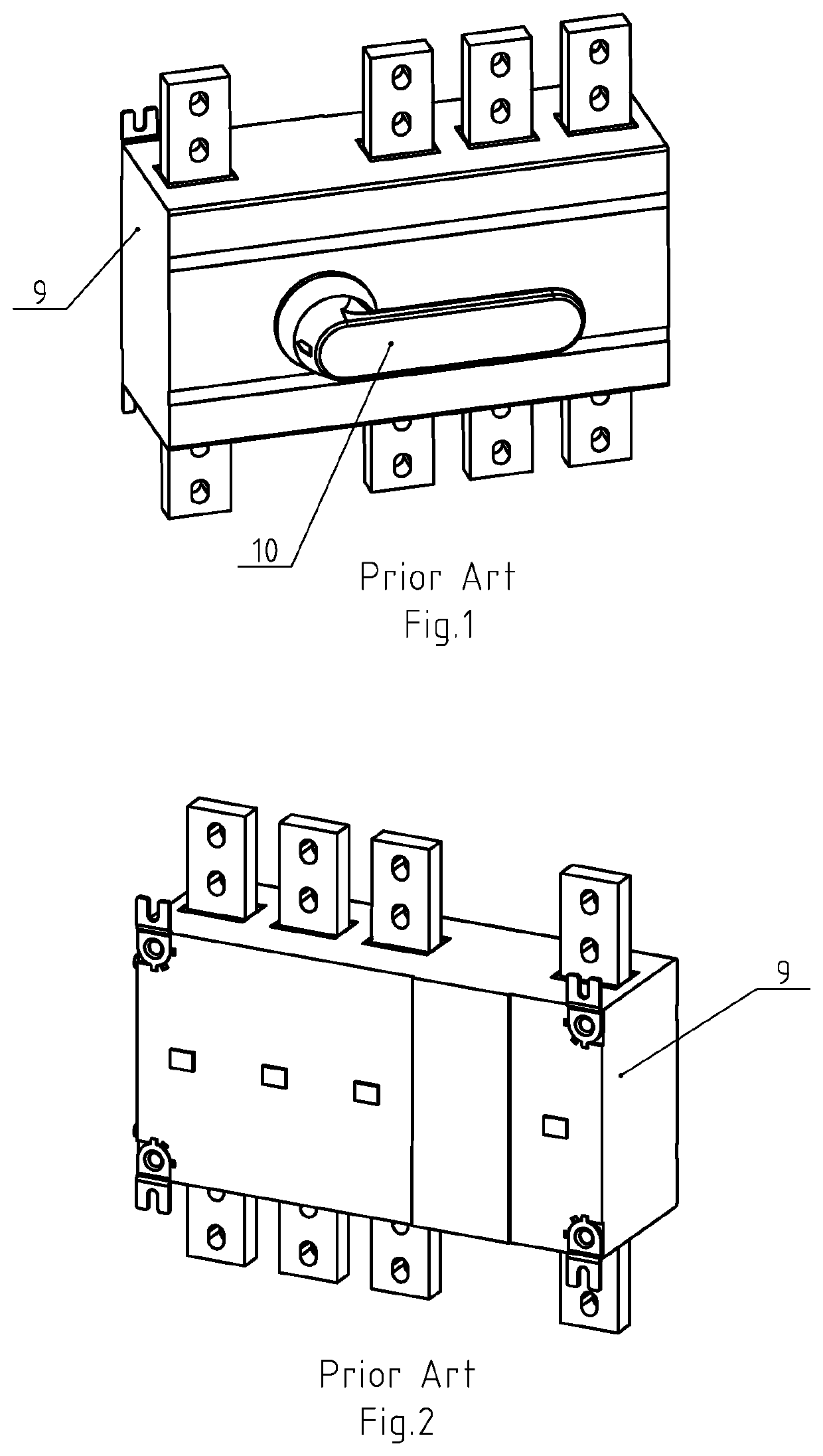
[0038]Referring to FIG. 1 and FIG. 2, it shows a traditional switch device, the device comprises four poles and a handle 10 between two poles, each one of four poles comprises two wiring terminals for connecting busbars and a switching unit arranged between the two wiring terminals for connecting or disconnecting the two wiring terminals, the switching unit comprises a movable contact connecting with a first wiring terminal, a stationary contact connecting with a second wiring terminal, and a shell 9 housing the movable contact and the stationary contact, the handle 10 controls a movement of the movable contact, the first wiring terminal and the second wiring terminal partially expose the housing.

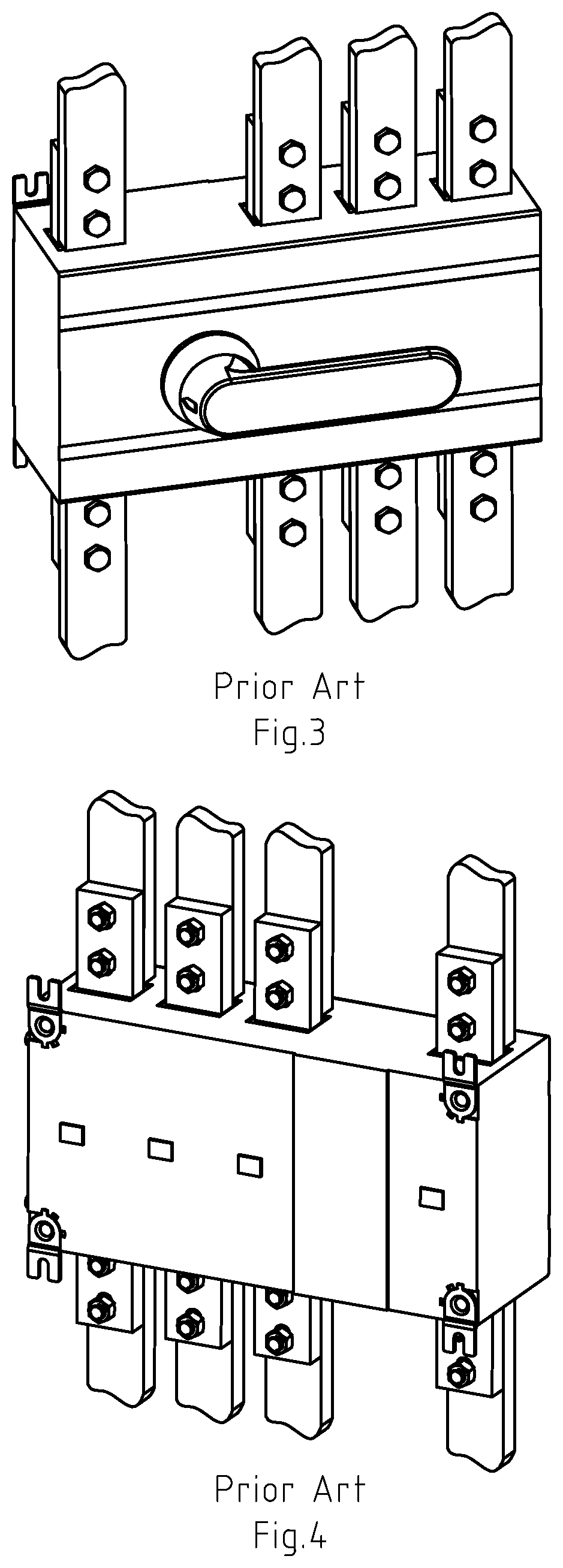
[0039]Referring to FIG. 3 and FIG. 4, it shows a connecting method between the wiring terminal of the traditional switch device and the busbars, an overlapping connecting method is applied, partly overlapping the wiring terminal and the busbar and then fastening them via bolts and nuts, suc...

embodiment 2

[0070]The material of the first column portion 1 in embodiment 1 is replaced by a copper alloy, and the material of the second column portion 2 in embodiment 1 is replaced by an aluminum alloy. Since a hardness of alloy is relatively high, the second column portion 2 is kept in a low temperature (5° C.) for a period of time (5 minutes), and the first column portion 1 is kept in a high temperature (80° C.) for a period of time (5 minutes), an inner diameter of the first column portion 1 is slightly increased and an outer diameter of the second column portion 2 is slightly reduced due to thermal expansion and contraction so as to conveniently assemble the second column portion 2 into the first column portion 1, when a temperature of assembled connecting rod returns to a normal temperature, an interference fit is formed between the first 1 and second 2 column portion. There are several different kinds of diameters and lengths of the connecting rod so as to meet different size of busbar...


PUM

PropertyMeasurementUnit
thermal expansion coefficientaaaaaaaaaa
resistivityaaaaaaaaaa
outer diameteraaaaaaaaaa

Abstract

A device has a wiring terminal for connecting a busbar, the wiring terminal has a connecting rod, which partly inserts into the wiring terminal and has an interference fit with the wiring terminal, the connecting rod has a conductive first column portion that has an interference fit with the busbar, the first column portion axially arranges a conductive second column portion that has an interference fit with the first column portion, the second column portion is located inside of the first column portion, a thermal expansion coefficient of the second column portion is greater than that of the first column portion, a resistivity of the second column portion is greater than that of the first column portion, a material of the second column portion is an aluminum or an aluminum alloy, and a material of the first column portion is a copper or a copper alloy.

Description

CROSS-REFERENCE TO RELATED APPLICATIONS[0001]This application is a continuation-in-part of U.S. patent application Ser. No. 16 / 442,478, filed Jun. 15, 2019, which is a continuation of U.S. patent application Ser. No. 15 / 920,472, filed Mar. 14, 2018, which is a continuation of U.S. patent application Ser. No. 15 / 602,146, filed May 23, 2017, which claimed priority to China Patent Application No. 2016103520134, filed May 24, 2016, the entire content of related applications are hereby incorporated by reference.BACKGROUND OF THE INVENTION[0002]The invention relates to an electric device, especially to a switch device.[0003]In the field of power distribution, a switch device is installed in a switch cabinet, a wiring terminal of the switch is usually directly connected with a power busbar, the power busbar is directly overlapped on the wiring terminal, the wiring terminal and the power busbar are commonly connected by an overlapping joint method, and then a bolt and a nut are used for fas...

Claims


Application Information

Patent Timeline
Patent Type & Authority Applications(United States)
IPC IPC(8): H01R25/16H01F27/29H01R25/14H01R4/42H01R4/00H01R4/62
CPCH01R4/42H01R25/145H01R4/54H01F27/29H01R4/36H01R11/28H01R25/162H01R4/62H01R13/04H01R13/03H01R4/48
Inventor ZHU, GONG
Owner ZHU GONG
Why Eureka
Try Eureka