Eureka AIR delivers breakthrough ideas for toughest innovation challenges, trusted by R&D personnel around the world.

Wet sludge drying method and fluidized bed dryer

Inactive Publication Date: 2020-12-10
SHAANXI XUANYI ENVIRONMENTAL TECH CO LTD
View PDF1 Cites 0 Cited by
  • Summary
  • Abstract
  • Description
  • Claims
  • Application Information

AI Technical Summary

Benefits of technology

The present invention provides a drying method and a fluidized bed dryer for wet sludge that can use solid particles at a medium temperature as heat carriers. This can reduce the risk of industrial accidents and greatly improve the safety of wet sludge drying. The problem of particles at a medium temperature and flammable sludge can also be solved by this invention.

Problems solved by technology

However, defects may be caused by the above characteristics.
However, the higher the inlet temperature is, the greater the possibility of ignition or even deflagration is.
Since the feeding point is limited in its number due to particles at extremely high temperature, a high-temperature zone is easily formed near the feeding point, leading to a trend of combustion or even explosion of wet sludge here.
Meanwhile, the entry of wet sludge from a high temperature end will cause particles burst rapidly due to the rapid evaporation of water.
Once it is dried out, the temperature will rise rapidly when it is heated again, rendering it more dangerous.
However, in a thin and long channel, it is required for particles to have an average lateral travel rate of greater than 0.05 m / s, which requires a very high fluidization speed and a very large power.
Therefore, the standard-state fluidization speed of 0.1-0.4 m / s is no longer enough.

Method used


Image

  • Wet sludge drying method and fluidized bed dryer

Examples


Embodiment Construction

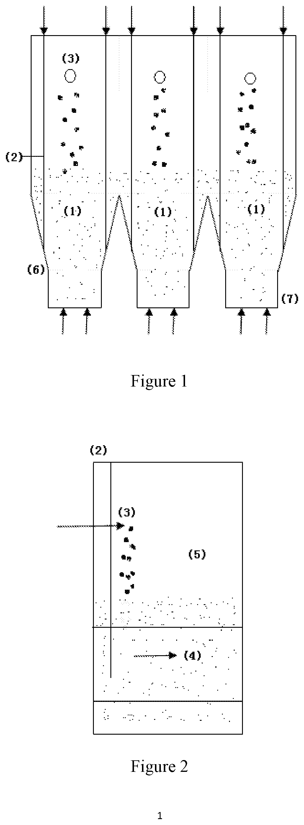
[0024]The principle underlying the present invention is that the particles as heat carriers are required to enter via scattered and multiple feeding points and enter the most intense backmixing area in the fluidized bed in a form of underflow.

[0025]The scattered multiple feeding points may be realized by processing in separate channels and multiple entry of solid particles as heat carriers through many points. In addition, entering the most intense backmixing area in the fluidized bed in a form of underflow specifically means that the entry points are in the downward area below the middle part of the dense phase zone in the fluidized bed, and solid particles as heat carriers flow downward after entry, and then are driven by rising bubbles and emulsion packets to the surface of the dense phase zone, where the temperature difference between the solid particles and surrounding particles is less than 100° C.

[0026]Wet sludge and particles as heat carriers are fed in the same area to form...


PUM


Abstract

A fluidized bed dryer, comprising at least two channels (1) connected in parallel; at least one wet sludge inlet (3) is provided at the tops of dilute phase zones (5) or above the dilute phase zones (5) in the channels (1), and at least one solid particle heat carrier and one material outlet are provided in dense phase zones (4) in the channels (1); the channels (1) are physically separated, from the middles of the dense phase zones (4) to the bottoms of the dense phase zones (4), in the material flow direction; the width of the bottoms of the dense phase zones (4) is less than the width of the tops of the dense phase zones (4) of the channels (1); the sum of the surface widths of the dense phase zones (4) of the channels (1) is greater than the flow length of sludge and the solid particle heat carrier in the flow direction; the height difference between solid particle heat carrier inlets (6) and air inlets (7) below the dense phase zones should be less than ¾ of the height of a material in the dense phase zones (4) when the material is stationary, and the distance between the solid particle heat carrier inlets and the side walls is no more than 10 cm. Further disclosed is a wet sludge drying method.

Description

TECHNICAL FIELD[0001]The invention relates to a drying method and a fluidized bed dryer for wet sludge, especially, a method for drying wet sludge by using particles at a medium temperature, and a fluidized bed dryer for sludge in which multi-channels containing particles at a medium temperature as heat carriers are parallel.BACKGROUND[0002]The fluidized bed dryer for sludge by using solid particles as heat carriers has many advantages over that having thermally conductive oil and steam as heat carriers. A good fluidized bed dryer for sludge by using solid particles as heat carriers requires the characteristics that follows sludge, particles and fluidized bed.[0003]Patent CN203007102U proposed a fluidized bed dryer for sludge by using particles as heat carriers, wherein, in addition to the dense phase zone, settling section and air distribution device which are commonly used by the fluidized bed equipment, this dryer has the following basic characteristics: particles at a high tempe...

Claims


Application Information

Patent Timeline
IPC IPC(8): C02F11/13
CPCC02F2303/06C02F11/13C02F11/16
Inventor YU, GUOHAOZHANG, DONGMEI
Owner SHAANXI XUANYI ENVIRONMENTAL TECH CO LTD
Why Eureka
Eureka Blog
Learn More