Supercharge Your Innovation With Domain-Expert AI Agents!

Intumescent battery pad

Pending Publication Date: 2020-12-10
ROGERS CORP
View PDF0 Cites 0 Cited by
  • Summary
  • Abstract
  • Description
  • Claims
  • Application Information

AI Technical Summary

Benefits of technology

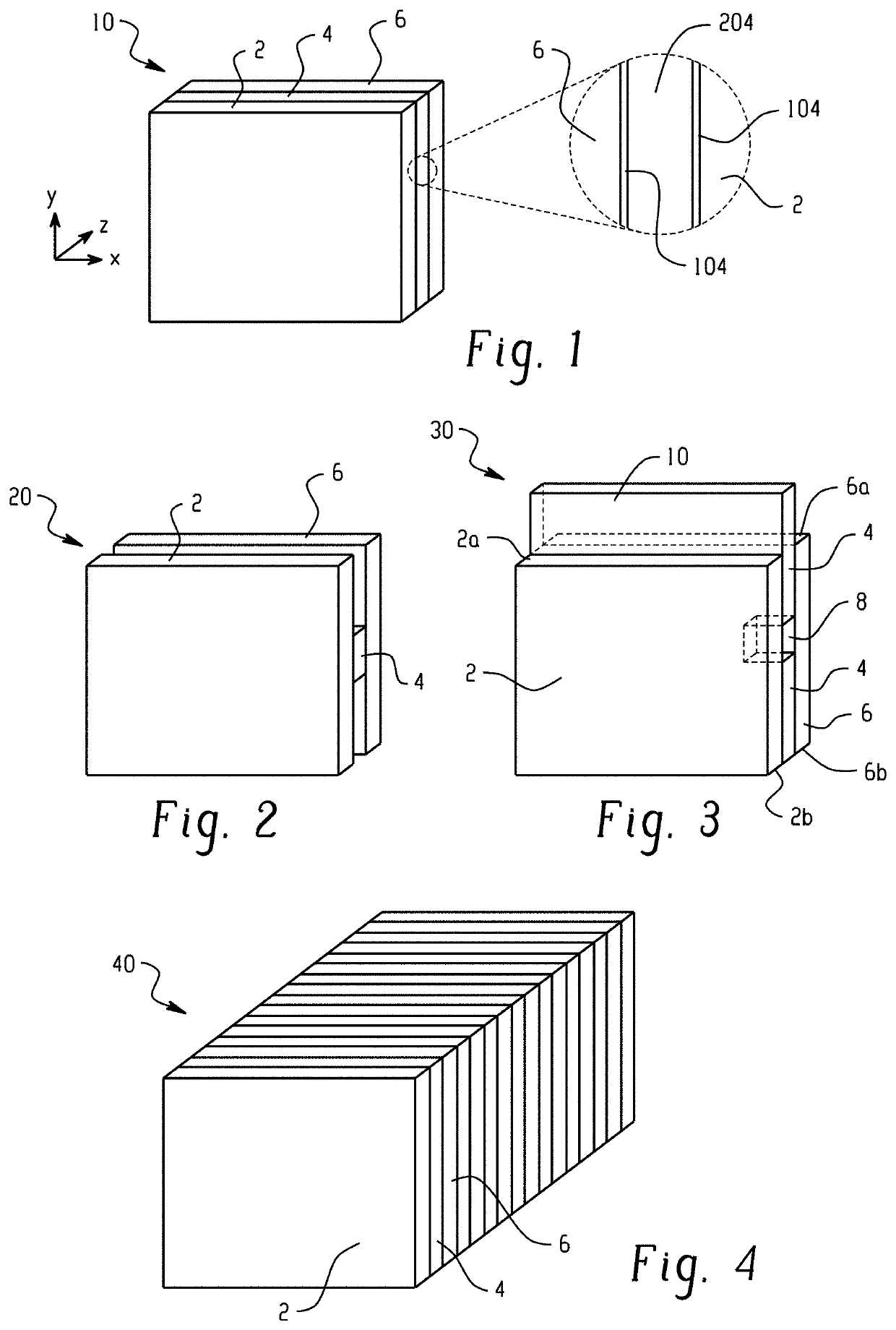
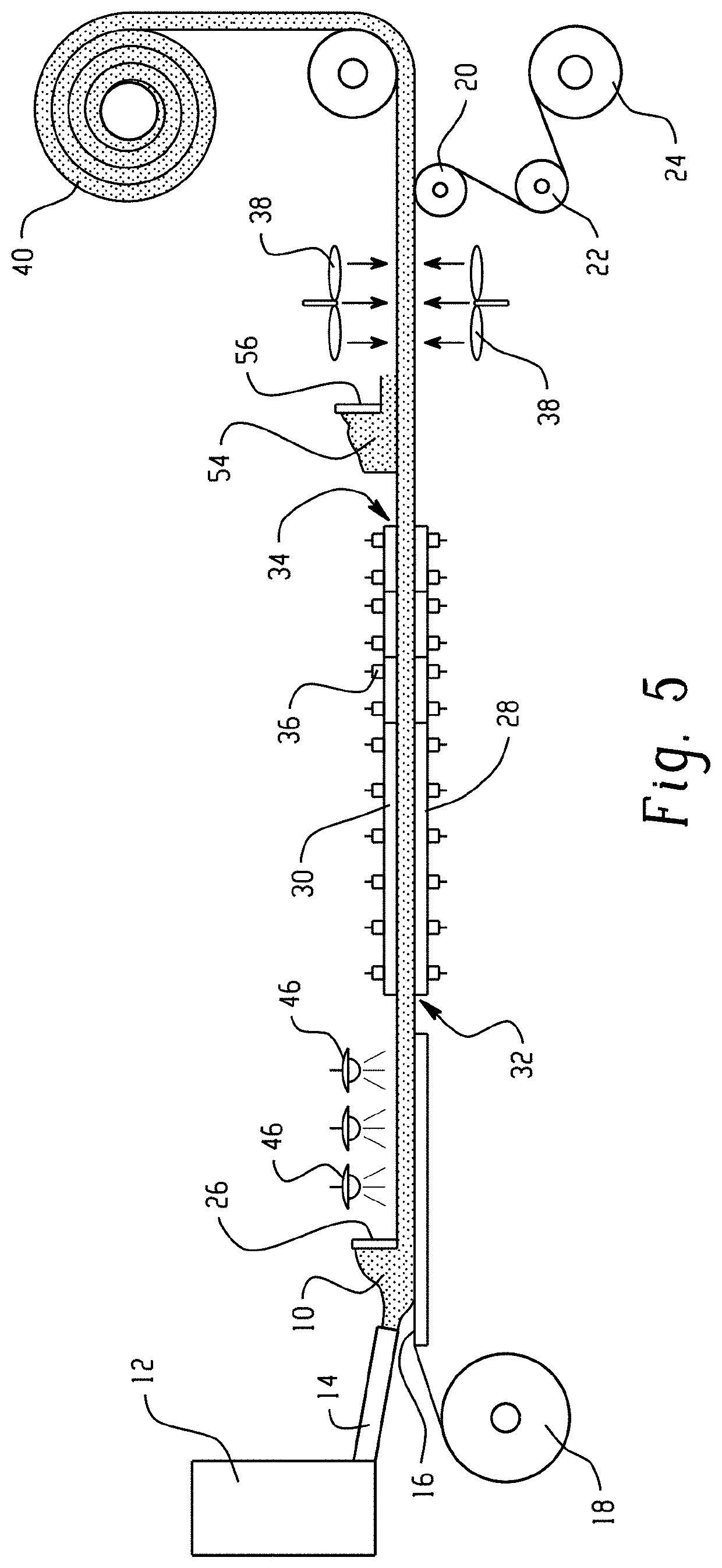
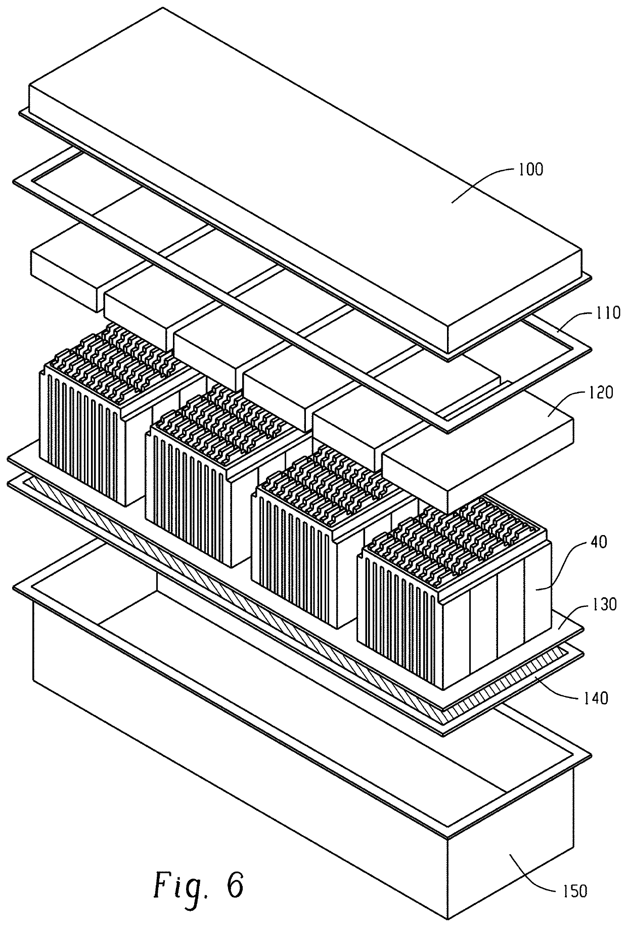
The patent describes an intumescent battery pad for lithium-ion batteries that has a polyurethane foam with a compression force deflection of 5 to 1, and an intumescent material made of acid, carbon, and a blowing agent. The battery pad has a UL-V0 rating at a thickness of 1 millimeter. The patent also describes a method of making the battery pad by coating a reactive mixture onto a release liner and curing it to form the foam, or by depositing the intumescent material on the foam. A battery assembly comprising at least two battery cells and an intumescent battery pad placed between or along the surface of the battery cells is also described. The technical effect of this patent is to provide an improved safety feature for lithium-ion batteries in the event of a fire or other abnormal conditions, as the intumescent material can provide a barrier to reduce the risk of flammability and minimize the spread of fire.

Problems solved by technology

An ongoing issue for large cells is safety, as the energy released in a cell going into thermal runaway is proportional to the amount of electrolyte and active materials that reside inside the cell and that are accessible during thermal runaway.
In other words, because larger cells contain a greater amount of the electrolyte and active material, thermal runaway can result in a more intense fire.
In addition, once a large cell is in thermal runaway mode, the heat produced by the cell can induce a thermal runaway propagation reaction in adjacent cells, causing a cascading effect igniting the entire pack, resulting in destruction to the pack and surrounding equipment, as well as potentially unsafe conditions for users.
While attempts to reduce the flammability of such batteries have been considered, they are not without their drawbacks.
For example, modifying the electrolyte by adding flame retardant additives or by using inherently non-flammable electrolytes have been considered, but these attempts can negatively impact the electrochemical performance of the lithium ion battery cell.
These approaches can limit the upper bounds of the energy density that can be achieved.
With the increasing demand for batteries with high energy densities, there is an increasing risk for flame occurrence and propagation.

Method used


Image

  • Intumescent battery pad
  • Intumescent battery pad
  • Intumescent battery pad

Examples


example 1

[0063]Seven PORON brand polyurethane foams were cut into strips having a thickness of 3 mm. An intumescent paint was spread onto the broad surfaces of three of the polyurethane foams and three of the polyurethane foams were dip coated into an intumescent paint. The seventh polyurethane foam did not comprise the intumescent paint.

[0064]The samples were then tested according to the Underwriter's Laboratory (UL)-94 flammability test at a thickness of 1 millimeter. FIG. 7 shows the samples after the flammability test, where the three polyurethane foams on the left were painted and the three polyurethane foams on the right were dip coated. The dip coated polyurethane foams achieved a UL-94 V0 rating and show a relatively small amount of char at the top of the foams. The painted polyurethane foams achieved a UL-94 V1 rating, where FIG. 7 shows some charring, especially towards the top of the foams. This increased charring relative to the dip coated foams is due to the fact that the edges ...


PUM


Abstract

In an aspect, an intumescent battery pad for a lithium ion battery comprises a polyurethane foam having a compression force deflection of 5 to 1,035 kilopascals at 25% deflection determined in accordance with ASTM D3574-17; and an intumescent material comprising an acid source, a carbon source, and a blowing agent; wherein the intumescent battery pad has a UL-V0 rating at a thickness of 1 millimeter. In another aspect, a battery can comprise at least two battery cells; and an intumescent battery pad located in between the at least two battery cells.

Description

CROSS-REFERENCE TO TECHNICALLY RELATED APPLICATION[0001]This application claims the benefit of U.S. Provisional Patent Application Ser. No. 62 / 859,230 filed Jun. 10, 2019. The related application is incorporated herein in its entirety by reference.TECHNICAL FIELD[0002]This application relates to an intumescent battery pad, a battery assembly, and in particular to a battery assembly including an intumescent battery pad that can be used in lithium ion batteries.BACKGROUND[0003]The demand for electrochemical energy storage devices, such as lithium-ion batteries, is increasing due to the growth of applications such as electric vehicles and grid energy storage systems, as well as other multi-cell battery applications, such as electric bikes, uninterrupted power battery systems, and lead acid replacement batteries. For large format applications, such as grid storage and electric vehicles, multiple cells connected in series and parallel arrays are often used. Such cells can be large (for e...

Claims


Application Information

Patent Timeline
IPC IPC(8): H01M2/16H01M10/0525H01M50/209H01M50/293H01M50/489
CPCH01M10/0525H01M2/1653H01M10/653H01M50/489H01M50/209H01M50/293H01M10/6235H01M10/658H01M10/659H01M10/052H01M50/24H01M50/116H01M50/411Y02E60/10
Inventor WANG, WEIKILHENNY, BRETTDAIGLE, ROBERTST. JEAN, MARKCHURCHILL, CHRISTOPHER
Owner ROGERS CORP
Features
  • R&D
  • Intellectual Property
  • Life Sciences
  • Materials
  • Tech Scout
  • Unparalleled Data Quality
  • Higher Quality Content
  • 60% Fewer Hallucinations
Learn More