
Spectroscopic analysis apparatus, spectroscopic analysis method, steel strip production method, and steel strip quality assurance method

a technology of spectroscopic analysis and analysis method, which is applied in the direction of optical radiation measurement, distance measurement, instruments, etc., can solve the problems of method not being able to eliminate disturbance, method not being able to calculate the intensity ratio with high accuracy, and method not being able to analyze the composition of the surface of the measurement target object with high accuracy. achieve the effect of high yield and high accuracy

Active Publication Date: 2020-12-17
JFE STEEL CORP
View PDF0 Cites 1 Cited by
  • Summary
  • Abstract
  • Description
  • Claims
  • Application Information

AI Technical Summary

Benefits of technology

The present invention provides a spectroscopic analysis apparatus and method that can accurately analyze the composition and composition ratio of a target object's surface, even in the presence of disturbances. Additionally, a steel strip production method enables the production of high-quality steel strips with desired surface compositions and ratios, while a steel strip quality assurance method ensures the provision of high-quality steel strips.

Problems solved by technology

Therefore, the method described in Patent Literature 1 fails to calculate the intensity ratio with high accuracy when the reflection spectrum intensity of s-polarized light is changed by a disturbance.
The method consequently fails to analyze the composition of the surface of a measurement target object with high accuracy.
In this measurement sequence, if a measurement target object is moving, it is also a disturbance because measurement on the same position is not possible.
Additionally, it is not possible to eliminate a disturbance such as vibration of a measurement target object.
Furthermore, when the number of times of switching polarizers is increased, measurement cycles are limited by process time of switching the polarizers.
As a result, an unmeasurable area where passed during the time of switching polarizers is increased.

Method used


Image

  • Spectroscopic analysis apparatus, spectroscopic analysis method, steel strip production method, and steel strip quality assurance method
  • Spectroscopic analysis apparatus, spectroscopic analysis method, steel strip production method, and steel strip quality assurance method
  • Spectroscopic analysis apparatus, spectroscopic analysis method, steel strip production method, and steel strip quality assurance method

Examples


Embodiment Construction

[0031]The principle of a spectroscopic analysis method according to aspects of the present invention is described hereinbelow.

[0032]When a measurement target object is of a metal material, the irradiated infrared light undergoes a 180° phase change due to the interaction with free electron in the metal. Therefore, when the electric field vector, that is, the polarization direction of the infrared light is perpendicular to an incident plane (p-polarized light), the electric field vector of the incident light and the electric field vector of the reflected light interfere with each other on the incident plane and a standing wave is formed. Consequently, a reflection spectrum contains information of a thin film on the incident plane.

[0033]In contrast, when the electric field vector of the infrared light is parallel to the incident plane (s-polarized light), the electric field vectors do not interfere with each other, whereby a reflection spectrum does not contain information of the thin...


PUM


Abstract

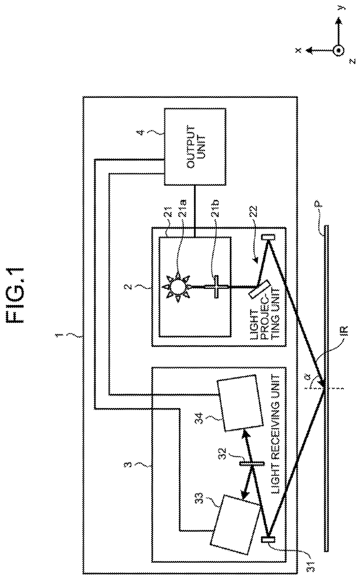
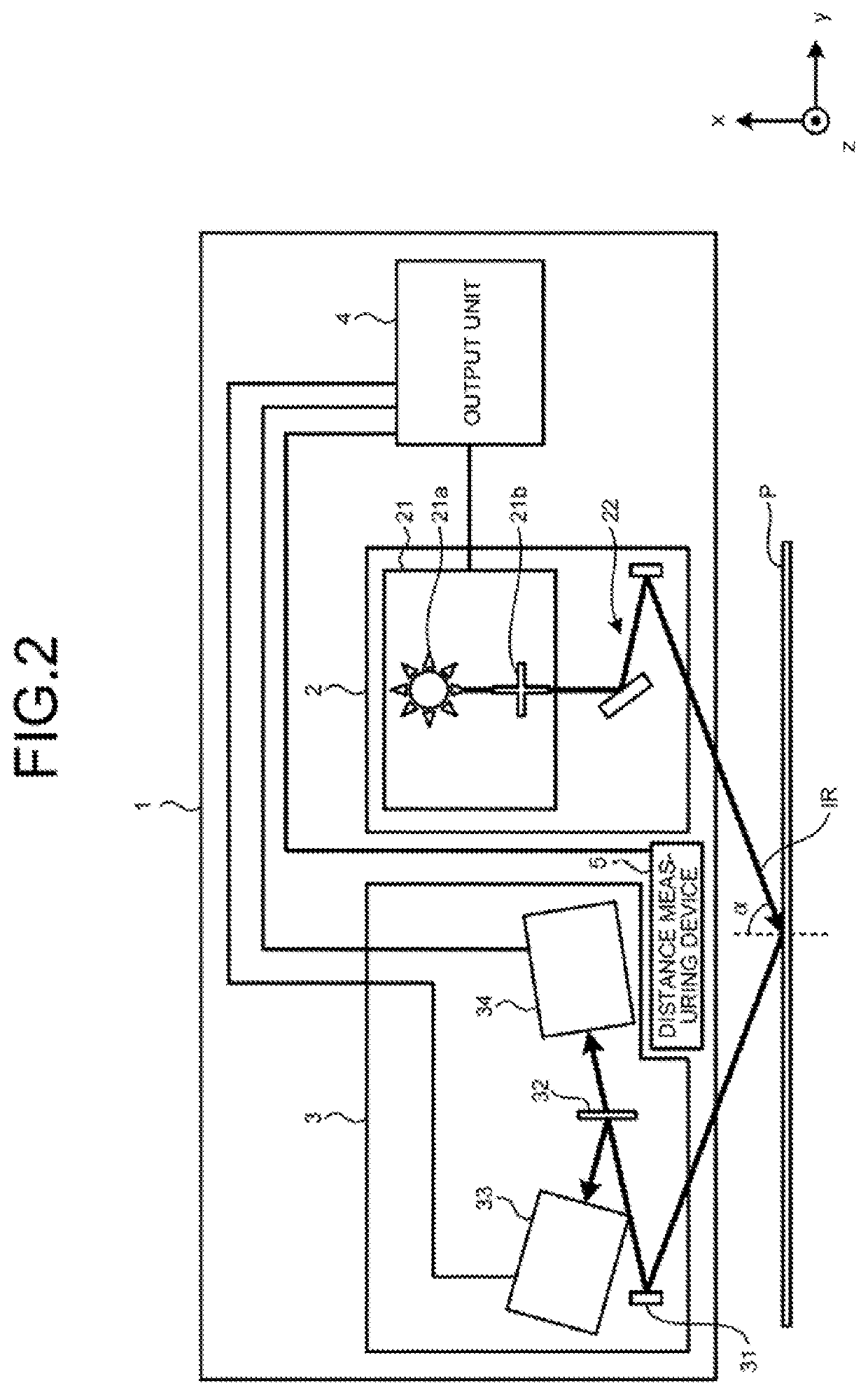
A spectroscopic analysis apparatus includes: a light projecting device; a light receiving device; and an output device, wherein the light receiving device includes: a separator configured to separate reflected light into s-polarized light and p-polarized light; a detector for s-polarized light configured to output an electric signal indicating an intensity of the s-polarized light; and a detector for p-polarized light configured to output an electric signal indicating an intensity of the p-polarized light; and the output device is configured to: calculate an absorbance based on a ratio between the intensities of the s-polarized light and the p-polarized light using the electric signals output from the detector for s-polarized light and the detector for p-polarized light; and calculate either or both of the composition and the composition ratio of the surface of the measurement target object using an intensity of the absorbance at any desired wavenumber.

Description

CROSS REFERENCE TO RELATED APPLICATIONS[0001]This is the U.S. National Phase application of PCT / JP2018 / 046266 filed Dec. 17, 2018, which claims priority to Japanese Patent Application No. 2018-006528, filed Jan. 18, 2018, the disclosures of these applications being incorporated herein by reference in their entireties for all purposes.FIELD OF THE INVENTION[0002]The present invention relates to a spectroscopic analysis apparatus, a spectroscopic analysis method, a steel strip production method, and a steel strip quality assurance method that are to be used for analyzing either or both of the composition and the composition ratio of the surface of a measurement target object.BACKGROUND OF THE INVENTION[0003]Patent Literature 1 describes a method for analyzing the composition of the surface of a measurement target object. Specifically, the method described in Patent Literature 1 measures, while p-polarized light polarized in parallel to an incident plane and s-polarized light polarized...

Claims


Application Information

Patent Timeline
IPC IPC(8): G01N21/3563G01N21/21G01N33/202G01C3/02
CPCG01N2201/063G01N21/3563G01N21/21G01N2201/061G01C3/02G01N33/202G01N21/86G01N21/8914G01N2021/8918G01N2021/8848G01N33/20G01J3/0224G01J3/42
Inventor NISHIZAWA, YUJITSUJI, SHOTAKATO, KAHO
Owner JFE STEEL CORP
Learn More