Eureka AIR delivers breakthrough ideas for toughest innovation challenges, trusted by R&D personnel around the world.

Pultrusion of Profiles Having Non-Uniform Cross Sections

Pending Publication Date: 2020-12-24
GALACTIC CO LLC
View PDF1 Cites 2 Cited by
  • Summary
  • Abstract
  • Description
  • Claims
  • Application Information

AI Technical Summary

Benefits of technology

The present invention is a pultrusion process and method that addresses problems in prior art approaches by sequentially pultruding different parts of a profile. By doing so, the process optimizes productivity and consistency, resulting in better airfoaI or other composite profiles. In one embodiment, a separate die is used to pultrude a thicker cross section leading edge slug before integrating it into the thinner or hollow section of the profile body. This prevents binding mandrels and ensures a better shape of the airfoil or other composite profile. The process is also less congested, leading to higher productivity and less downtime for corrective action.

Problems solved by technology

Non-uniform cross-section pultrusions must be processed slower because the speed is limited by the time for curing the thickest portion of the cross section of the pultruded part.
Therefore, the lack of an efficient method for pultrusion of non-uniform cross sections has been a limitation, for example, in the aerospace and aviation industry.
However, manufacturing non-uniform cross sections presents a processing challenge for conventional pultrusion using a single die.
Profiles with non-uniform cross sections are more challenging to produce with high yields and consistency.
In addition, in some cases, additional leading edge weight must be added to the composite leading edge slug.
Other pultruded applications may have the same issue where a spar area requires a heavy cross section for strength, while other areas need to be thin and light weight.
While demonstrations of profiles having these non-uniform cross sections has been done as part of research and development efforts using a traditional single die, use of a single die can be problematic for consistent high volume production.
Further, prior art non-uniform cross sections manufactured using a typical single pultrusion die have proven problematic for multiple reasons.
With a single pultrusion die, the productive line speed is limited by the curing of the thickest cross section.
Therefore, pultruding a profile with both thin and thick portions requires compromising on these choices.
Thus, fewer options are available to optimize the pultrusion of the thick and thin sections of the airfoil or other profiles when it is done in the same die.
Third, the de-bulking action of pulling the large mass of leading edge slug fibers into the typical single die tends to displace the die mandrels towards the trailing edge of the outer mold line portion of the die, thus increasing pull loads, binding the profile, and potentially creating a non-straight airfoil.
Fourth, when thick and thin cross sections are pultruded at the same time there is greater drag or pull force for the thick section, which can result in a curved finished profile.
Thus, using a single die for manufacturing pultruded parts of this type is slow and is prone to downtime and the need for corrective action, which leads to inconsistent product and yield.

Method used


Image

  • Pultrusion of Profiles Having Non-Uniform Cross Sections
  • Pultrusion of Profiles Having Non-Uniform Cross Sections
  • Pultrusion of Profiles Having Non-Uniform Cross Sections

Examples


Embodiment Construction

[0039]The following is a detailed description of embodiments to illustrate the principles of the invention. The embodiments are provided to illustrate aspects of the invention, but the invention is not limited to any embodiment. The scope of the invention encompasses numerous alternatives, modifications, and equivalents. The scope of the invention is limited only by the claims.

[0040]While numerous specific details are set forth in the following description to provide a thorough understanding of the invention, the invention may be practiced according to the claims without some or all of these specific details.

[0041]Various embodiments will be described in detail with reference to the accompanying drawings. Wherever possible, the same reference numbers are used throughout the drawings to refer to the same or like parts. References made to particular examples and implementations are for illustrative purposes and are not intended to limit the scope of the claims.

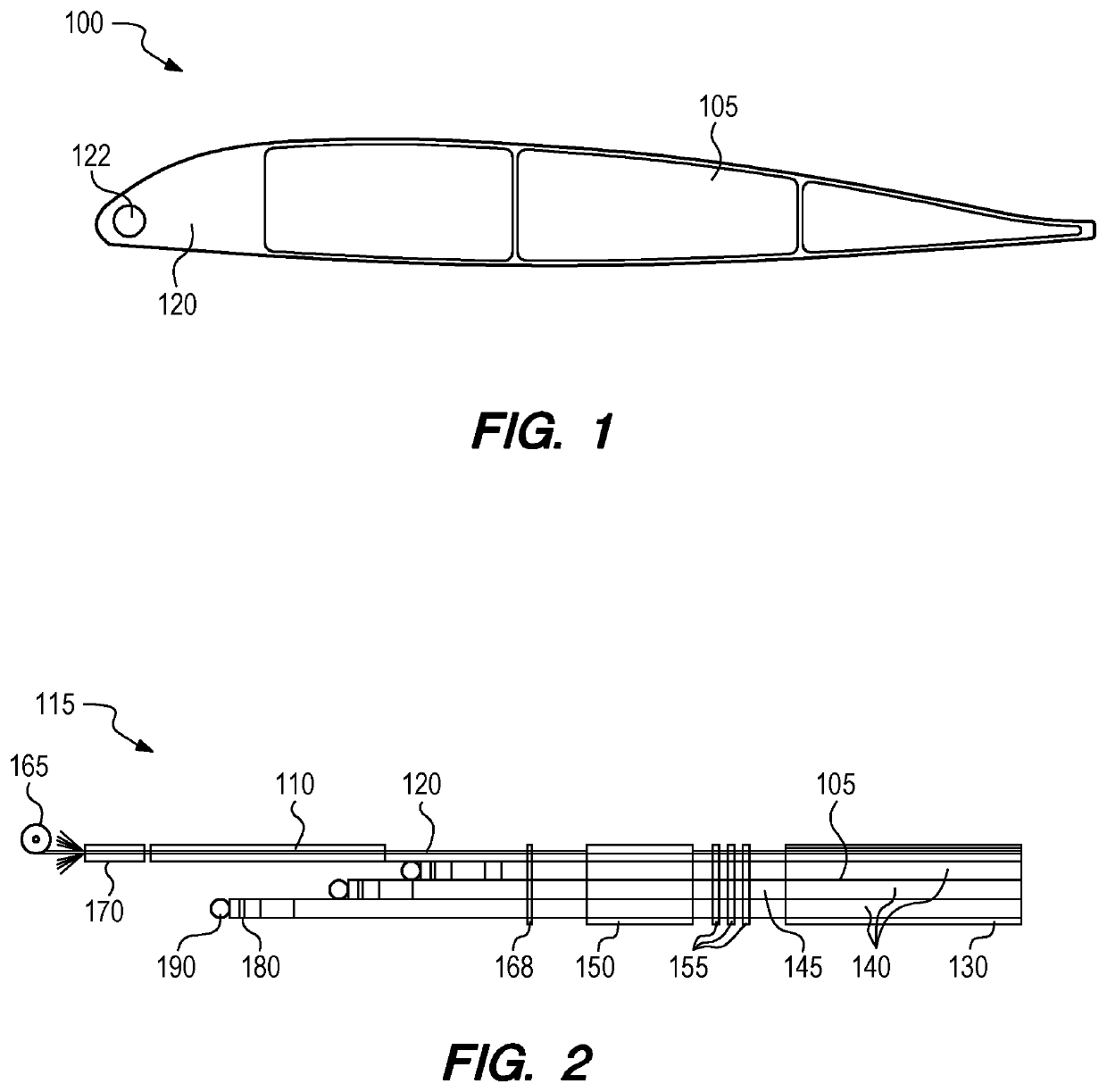
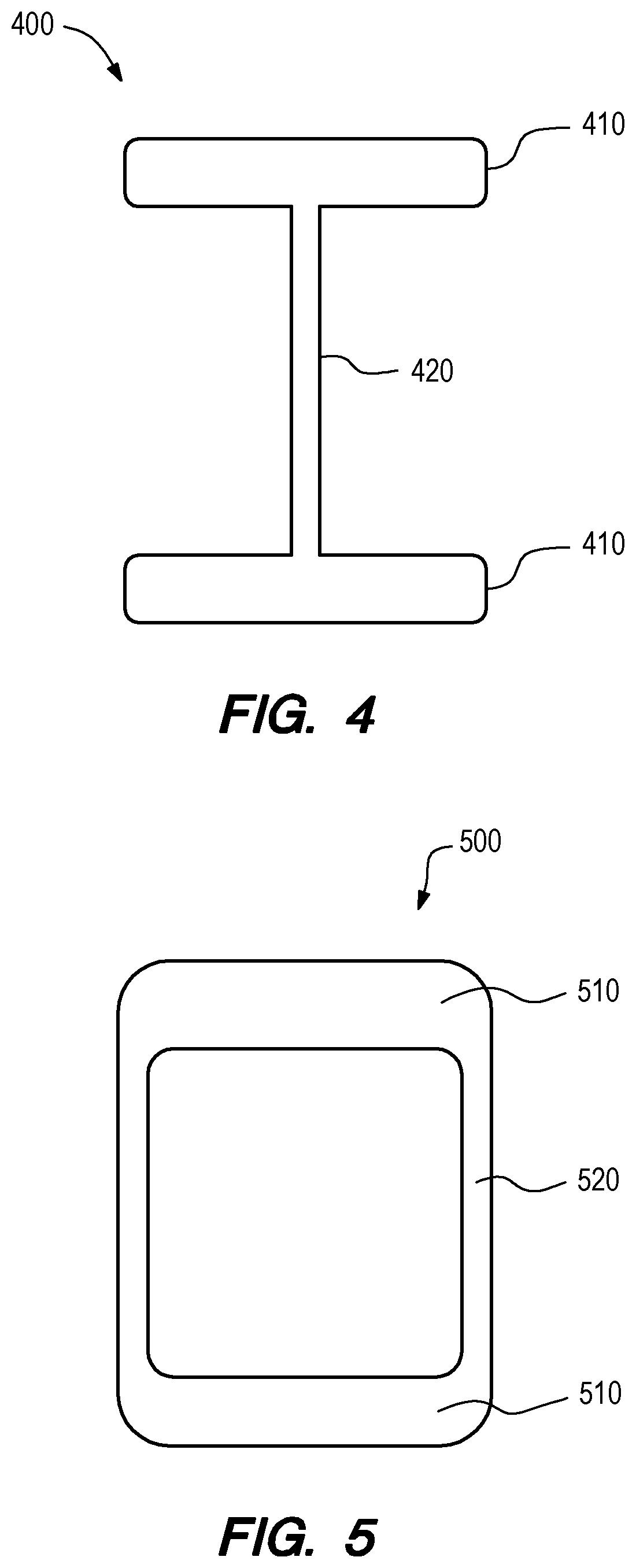
[0042]Composite Profiles...


PUM

PropertyMeasurementUnit
Weightaaaaaaaaaa
Lengthaaaaaaaaaa

Abstract

Composite profiles, such as rotor blades, airfoils, I-beams, and box beams having non-uniform cross sections, and a system, method and process for pultrusion of composite profiles. The pultrusion of a heavier or thicker cross section portion of the composite profile is performed in-line and upstream from pultrusion of a thinner or lighter portion of the pultruded profile using a separate die for the thicker portion of the cross section, or leading edge slug, in order to optimize the processing conditions, productivity, and consistency of the composite profiles.

Description

CROSS-REFERENCE TO RELATED APPLICATIONS[0001]This application claims priority under 35 USC Section 119(e) to co-pending U.S. Provisional Patent Application No. 62 / 864,285 filed on Jun. 20, 2019, the entire disclosure of which is incorporated herein by reference.FIELD OF THE INVENTION[0002]This invention relates generally to pultrusion methods for hollow and solid pultruded profiles, such as rotor blades, airfoils, I-beams, and box beams, having non-uniform cross sections, and hollow and solid pultruded profiles made by these pultrusion methods.BACKGROUND OF THE INVENTION[0003]Pultrusion is a continuous composite manufacturing process capable of making uniform and non-uniform cross section parts. Fibers, such as fiberglass or carbon fibers in various forms, are mechanically pulled through a resin bath, through shaping tooling, and through resin squeeze-out tooling. Then they pass through a heated steel die that cures the raw materials into a solid profile for use in various applicati...

Claims


Application Information

Patent Timeline
IPC IPC(8): F01D5/14B29C70/52
CPCB29L2031/003B29C70/521F05D2240/30F01D5/147B29K2309/08B29K2307/04B29K2063/00B64C2027/4736F03D1/0675B29C70/525B64C27/473B29D99/0028B29C70/52
Inventor SJOSTEDT, ROB
Owner GALACTIC CO LLC
Why Eureka
Eureka Blog
Learn More