
Device for optical inspection of empty and liquid-filled containers

a container and optical inspection technology, applied in the direction of measuring devices, material analysis through optical means, instruments, etc., can solve the problems of complex construction of inspection devices, limited maximum apertures, and negative impact on the uniform illumination of containers to be inspected, so as to reduce the probability of failure, reduce the effect of lighting effect and reliable identification

Active Publication Date: 2020-12-31
SEIDENADER MASCHINEBAU GMBH
View PDF0 Cites 7 Cited by
  • Summary
  • Abstract
  • Description
  • Claims
  • Application Information

AI Technical Summary

Benefits of technology

The present invention provides a device for optically inspecting containers that is simple and cost-effective. The device uses a two-dimensional light pattern consisting of at least two regions of different light intensities to illuminate the container and a camera to record the image. A mirror system is used to deflect the light from the illumination unit onto the recording apparatus, resulting in a compact construction of the device. The device can inspect containers that are empty or filled with liquid and ensures optimal illumination. The technical effects of the invention include improved inspection results, reduced image errors, and a more compact construction of the inspection system.

Problems solved by technology

When illuminating inspection systems of this kind, lens collimators are often used, which are, however, susceptible to image errors and, in limited installation space, require a complex construction of the inspection device that is necessary for folding the beam path.
Furthermore, the maximum apertures are limited in optical systems of this kind, and this has a negative impact on the uniform illumination of the containers to be inspected, in particular for moving containers which are intended to be illuminated and imaged at multiple positions along the movement path.
As a result, any inhomogeneities in the illumination that are potentially present (e.g. dust or other dirt, but also intensity gradients or patterns intentionally introduced by the light pattern) are not visible in the image recorded by the recording apparatus.
The limited installation space in a typical inspection device thus poses a problem since it requires short distances and thus short focal lengths.
The required diameters and refractive powers are unlikely to be achieved using cost-effective materials such as PMMA, and therefore high-index lenses are required.
Lastly, the distance of the container-side glass / air surface, which is shorter in a lens system, means that dirt (e.g. dust) is visible in the image on this surface due to the depth of focus of the recording apparatus focused on the container and the inspection results may be impacted negatively.
Considerably higher costs due to the material (high-index lenses), the number of optical surfaces and the required anti-reflective coating.
With high-index lenses, too, the apertures that can be achieved are limited, and therefore disadvantageous compromises have to be made when illuminating the containers.
Despite the coating, dust not only results in scattered light, but can also become directly visible in the image and result in incorrect inspections, since the distances from the lens surfaces are shorter than the distance from said container to an obliquely arranged mirror.
Despite the coating, there is the risk of faint ghosting, caused by the reflections on the very taut, i.e. highly curved surfaces of the lenses, which can result in defective inspection results.
For very compact constructions, an additional mirror may be required for folding, which further increases the costs.
However, there is no possibility of retroactive coating, which results in drawbacks with regard to ghosting and scattered light.
However, it is often recommended that protective glass be provided in a lens system, since the containers can get broken (e.g. breakage of glass) when installing the machines.
The illumination surface of the illumination unit would be interrupted at this point, which makes bright-field illumination impossible, for example.
However, this is only applicable as long as there is no material disrupting this beam path between the mirror system and the recording apparatus.
There is therefore a high probability that particles of this kind cannot be traced in every image in an image series and that incorrect results arise.

Method used


Image

  • Device for optical inspection of empty and liquid-filled containers
  • Device for optical inspection of empty and liquid-filled containers
  • Device for optical inspection of empty and liquid-filled containers

Examples


Embodiment Construction

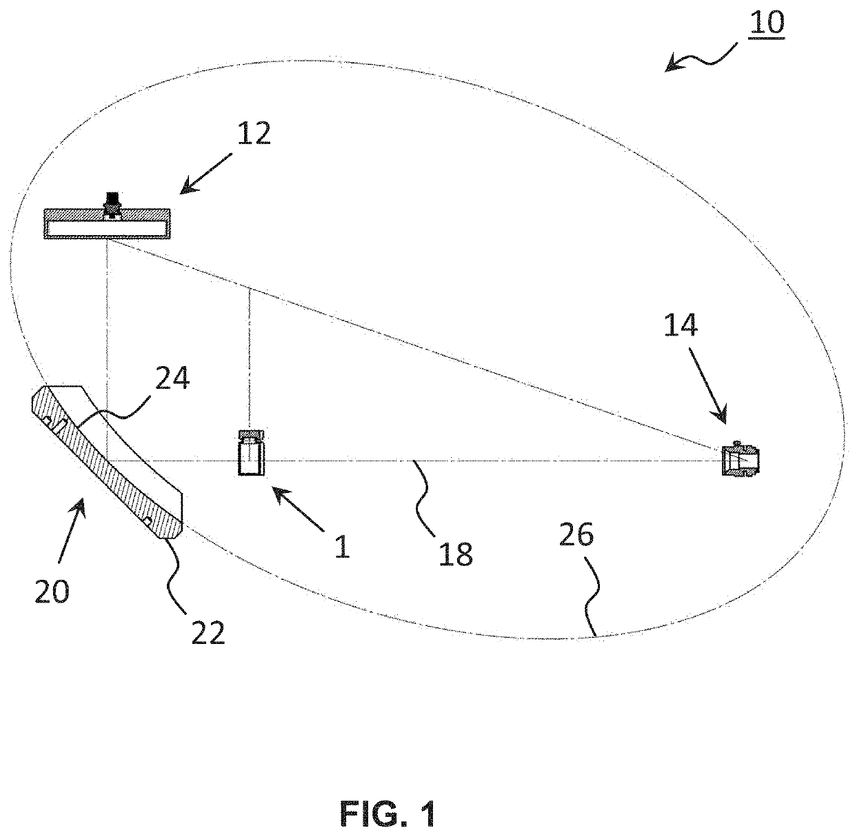
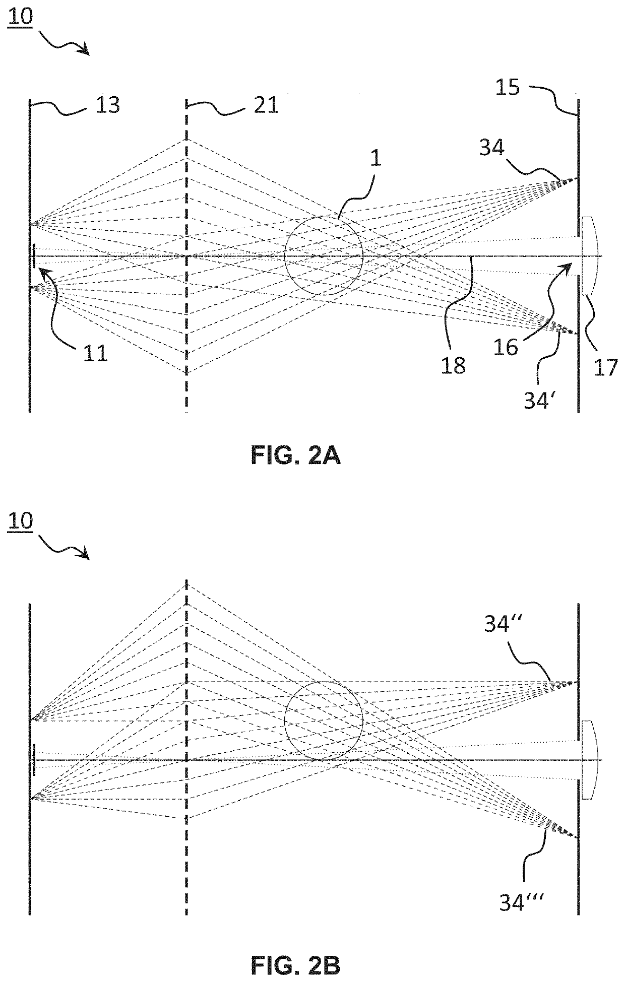
[0092]FIG. 1 is a side view of an embodiment of the device 10 according to the invention as a section along the plane of symmetry of the device 10. The device 10 is used for the automatic inspection of transparent, cylindrical containers 1, in particular medication containers such as ampoules, vials, syringes or cartridges, which may be empty or filled with a partially or completely transparent liquid. The device 10 according to the invention is therefore explicitly suitable for the inspection of cylindrical containers 1 filled with liquid.

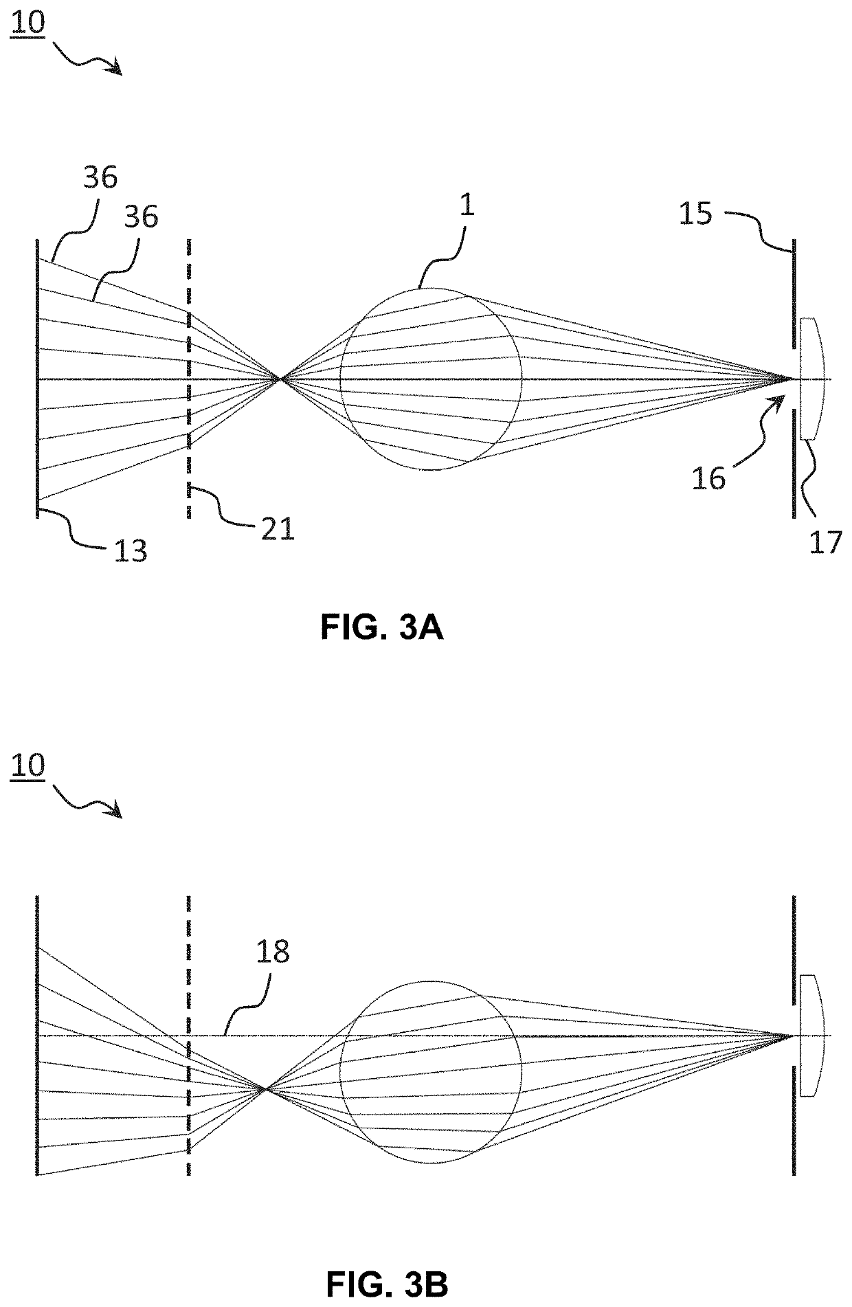
[0093]The device 10 comprises an illumination unit 12 comprising an illumination surface 13, which can e.g. be produced by a simple background light comprising a diffuser, a mirror system 20, functioning as a collimator, which comprises a single concave mirror 22 (one-mirror system) and a recording apparatus 14, which comprises a camera and a lens 17. A container 1 to be inspected, which in this case is arranged in the center of the camera field i...


PUM

PropertyMeasurementUnit
deflection angleaaaaaaaaaa

Abstract

The invention relates to a device for optically inspecting a container that is empty or filled with liquid, comprising an illumination unit and a recording apparatus. The illumination unit comprises an illumination surface, by means of which a two-dimensional light pattern consisting of at least two regions of different light intensities can be produced and the container can be irradiated with light from the light pattern, in particular said light can shine therethrough. According to the invention, a mirror system is further provided which is arranged in the beam path between the illumination unit and the container and comprises at least one concave mirror. The mirror system images the light pattern produced by the illumination unit onto the plane of the entrance pupil of the recording apparatus.

Description

CROSS-REFERENCE TO RELATED APPLICATION[0001]The present application claims priority to German Patent Application No. 10 2019 117 260.8 filed on Jun. 26, 2019. The entire contents of the above-listed application is hereby incorporated by reference for all purposes.TECHNICAL FIELD[0002]The present invention relates to a device for optically inspecting containers that are empty or filled with liquid according to the preamble of claim 1.BACKGROUND AND SUMMARY[0003]Fully automatic optical inspection systems are used in many technical sectors, such as the pharmaceutical industry, the beverage industry or the semiconductor industry in order to identify defective products and to eliminate these products from the further production processes. Generic inspection devices typically comprise a light source for illuminating the container to be inspected and a camera for recording an image of the container.[0004]When illuminating inspection systems of this kind, lens collimators are often used, wh...

Claims


Application Information

Patent Timeline
Patent Type & Authority Applications(United States)
IPC IPC(8): G01N21/956
CPCG01N21/956G01N2021/945G01N2021/9511G01N21/90
Inventor KNUELLE, MATTHIAS
Owner SEIDENADER MASCHINEBAU GMBH
Learn More