
Ventilator Setting Adjustment System

Pending Publication Date: 2021-01-14
MEDIPINES CORP
View PDF7 Cites 0 Cited by
  • Summary
  • Abstract
  • Description
  • Claims
  • Application Information

AI Technical Summary

Benefits of technology

The invention is about a ventilator that adjusts its settings based on the patient's breathing needs. It uses the ratio of CO2 to O2 in the patient's blood to determine the level of support it should provide. If the ratio is high, the ventilator increases pressure support, respiratory rate, and tidal volume to provide more support without a complete exhalation. Conversely, if the ratio is low, the ventilator decreases pressure support, respiratory rate, and tidal volume to avoid excessive respiratory effort. The ventilator can also adjust other settings such as FiO2, PEEP, and support to the patient based on the measured values of CO2 and O2 and the preferences of the operator. Overall, the invention allows for a more effective and efficient ventilatory support for patients.

Problems solved by technology

Unfortunately, many hospitals have low compliance conducting daily spontaneous breathing.
Some people never improve enough to be taken off the ventilator completely or at all.
However, currently there is no reliable way to set PEEP setting as it is based on clinician's judgment.
While widely used, there are serious limitations to this method.
For instance, based on this method, two patients of the same height that are critically ill, will receive the same starting volume, without considering that their lungs may have very different available volumes due to conditions such as pulmonary edema, which is fluid inside the lungs, thus resulting in more stretching of the lungs of one of the patients.
When patients can no longer maintain ventilation sufficient for the demand of their body, the result is respiratory failure.
If the PaO2 is equal to or lower than the PaCO2, respiratory failure and the need for further intervention are likely.

Method used


Image

  • Ventilator Setting Adjustment System
  • Ventilator Setting Adjustment System
  • Ventilator Setting Adjustment System

Examples


Embodiment Construction

[0041]The following discussion provides many example embodiments of the inventive subject matter. Although each embodiment represents a single combination of inventive elements, the inventive subject matter is considered to include all possible combinations of the disclosed elements. Thus if one embodiment comprises elements A, B, and C, and a second embodiment comprises elements B and D, then the inventive subject matter is also considered to include other remaining combinations of A, B, C, or D, even if not explicitly disclosed.

[0042]As used in the description herein and throughout the claims that follow, the meaning of “a,”“an,” and “the” includes plural reference unless the context clearly dictates otherwise. Also, as used in the description herein, the meaning of “in” includes “in” and “on” unless the context clearly dictates otherwise.

[0043]Unless the context dictates the contrary, all ranges set forth herein should be interpreted as being inclusive of their endpoints, and ope...


PUM


Abstract

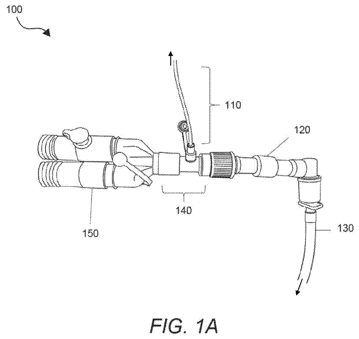
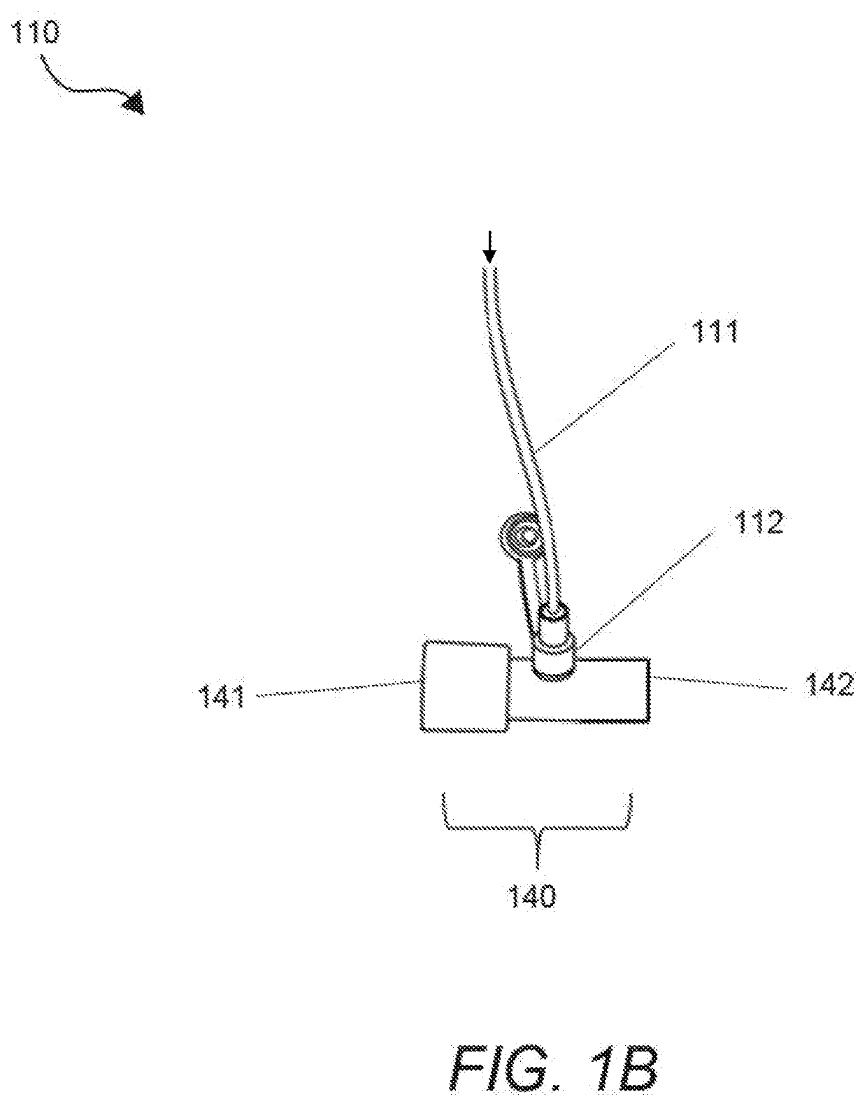
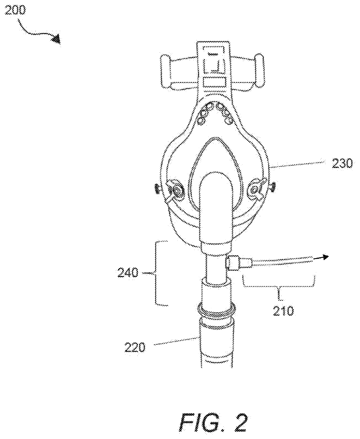
An automatic ventilator adjusting system has a three-way inline adapter coupled to 1) a breath sample line, 2) a ventilator (either invasive or non-invasive), and 3) a patient. The breath sample line is coupled to a Gas Exchange Monitor (GEM) and preferably has a female Luer lock end. Ventilator settings can be automatically set and / or adjusted using 1) an algorithm preferably having a feedback loop and 2) inputs including one or more of: gPaO2™ (calculated arterial partial pressure of O2 by GEM), oxygen deficit, gPaCO2™ (calculated arterial partial pressure of CO2), gPaCO2™ / gPaO2™, PiO2-PETO2, TLC (Total Lung Capacity), FRC (Functional Residual Capacity), and Vd / Vt (deadspace ratio). Preferably, one or more of the inputs (e.g., gPaO2™ gPaCO2™, and oxygen deficit) are obtained non-invasively from a patient's normal breathing gas samples as calculated by MediPines Gas Exchange Monitor (GEM).

Description

CROSS-REFERENCE TO RELATED APPLICATIONS[0001]This application claims priority to U.S. Provisional Application Ser. No. 62 / 814,184, filed on Mar. 5, 2019, which is incorporated herein by reference in its entirety.FIELD OF THE INVENTION[0002]The field of the invention is ventilator setting adjustment.BACKGROUND[0003]The following background discussion includes information that may be useful in understanding the present invention. It is not an admission that any of the information provided herein is prior art or relevant to the presently claimed invention, or that any publication specifically or implicitly referenced is prior art.[0004]The mechanical ventilator (sometimes called respirator, breathing machine, ventilator, invasive ventilation etc.) is used primarily for treatment of patients in hospital setting, typically in Intensive Care Unit (ICU), Emergency Department or other area of the hospital where staff are specially trained to care for patients that have higher acuity than th...

Claims


Application Information

Patent Timeline
IPC IPC(8): A61M16/00A61M16/08
CPCA61M16/024A61M16/0858A61M16/085A61M16/0051A61M2205/583A61M2230/435A61M2230/42A61M2205/581A61M2230/432A61M16/0833A61M2230/205A61M2230/40A61M2016/1025A61M2205/3553A61M2205/3584A61M2205/3592A61M2205/502A61M16/04A61M16/0633A61M2230/202A61B5/0816A61B5/091A61B5/4836A61B5/14542A61M2230/005
Inventor LEE, STEVEHINDS, RICHARD
Owner MEDIPINES CORP
Learn More