Supercharge Your Innovation With Domain-Expert AI Agents!

Instantaneous ellipsometer or scatterometer and associated measuring method

a technology of instantaneous ellipsometry and scatterometer, which is applied in the field of optical instruments, can solve the problems of affecting measurement accuracy, modulation suffers from a certain number of drawbacks, and the use of an optical polarization modulator based on a rotating component may have drawbacks in terms of vibration generation, long-term reliability and robustness

Active Publication Date: 2021-01-14
HORIBA FRANCE SAS
View PDF0 Cites 5 Cited by
  • Summary
  • Abstract
  • Description
  • Claims
  • Application Information

AI Technical Summary

Benefits of technology

The patent describes an instrument called an ellipsometer that can measure the way light is bended when it passes through a certain material. This instrument allows for quick and easy measurements to be made without changing the way the light is polarized. The duration of the measurement can be adjusted based on the intensity of the light beams or spectral sub-images. The technical effect of this invention is that it provides a more efficient and accurate way to measure light properties in real-time.

Problems solved by technology

This approach, based on a temporal polarization modulation, however suffers from a certain number of drawbacks.
Firstly, the measurement accuracy is affected by the intensity instabilities of the light source used.
In particular, the use of an optical polarization modulator based on a rotating component may have drawbacks in terms of generation of vibrations but also in terms of long-term reliability and robustness.
Finally, during the acquisition a series of spectra over a modulation period, it is generally not possible to adjust the time of acquisition of a spectrum as a function of the intensity thereof, because the duration of acquisition of a spectrum is determined by the modulation period.
Hence, this approach does not make it possible to use the detector in a favourable intensity range of its dynamics for measuring each spectrum, avoiding the saturation while also avoiding a too low signal.
That way, it is sometimes difficult to examine with a same monochromatic or spectroscopic ellipsometer materials having very different reflectivity values or to use spots having very different sizes.
However, a wavefront-division polarimeter has for drawback that the light intensity distribution on the different spectral images strongly depends on the experimental conditions.
The state of polarization measurement by means of such a polarimeter may be inaccurate and / or erroneous.
Moreover, the insertion of the optical system is liable to reduce the light intensity of the beam, to limit the spectral band and / or to change the divergence of the light beam.

Method used


Image

  • Instantaneous ellipsometer or scatterometer and associated measuring method
  • Instantaneous ellipsometer or scatterometer and associated measuring method
  • Instantaneous ellipsometer or scatterometer and associated measuring method

Examples


first embodiment

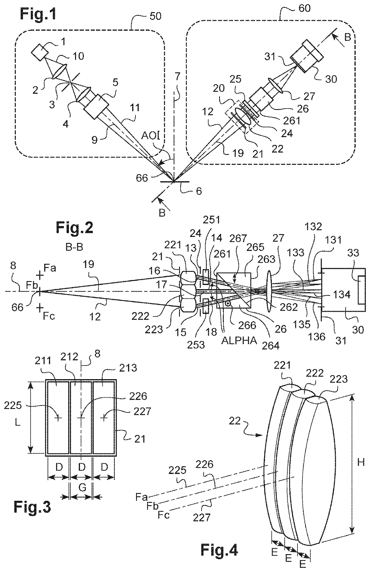
[0066]In FIGS. 1 to 5 is shown an ellipsometer or scatterometer according to a

[0067]The ellipsometer or scatterometer includes an illumination arm 50 and a detection arm 60 arranged on either side of a sample 6 that is to be measured. The illumination arm 50 includes a light source 1, a first optical system 2, a source diaphragm 3, another optical focusing system 4 and a polarizer 5. Preferably, the polarizer 5 is arranged downstream from the optical focusing system 4. As an alternative, the polarizer 5 can be arranged upstream from the optical focusing system 4 or between different components of the optical focusing system 4.

[0068]The light source 1 emits a source light beam 10, preferably in a spectrally extended wavelength range, for example from 360 nm to 700 nm for a xenon flash lamp. The first optical system 2 forms the image of the source on the source diaphragm 3. As an alternative, a fibred light source whose end forms the source diaphragm 3 is used. The light source 1 can ...

second embodiment

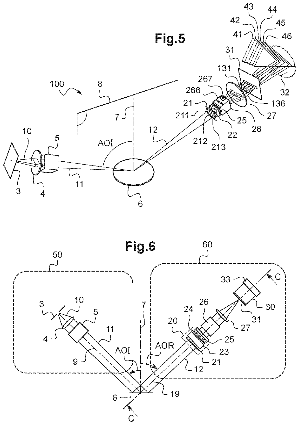
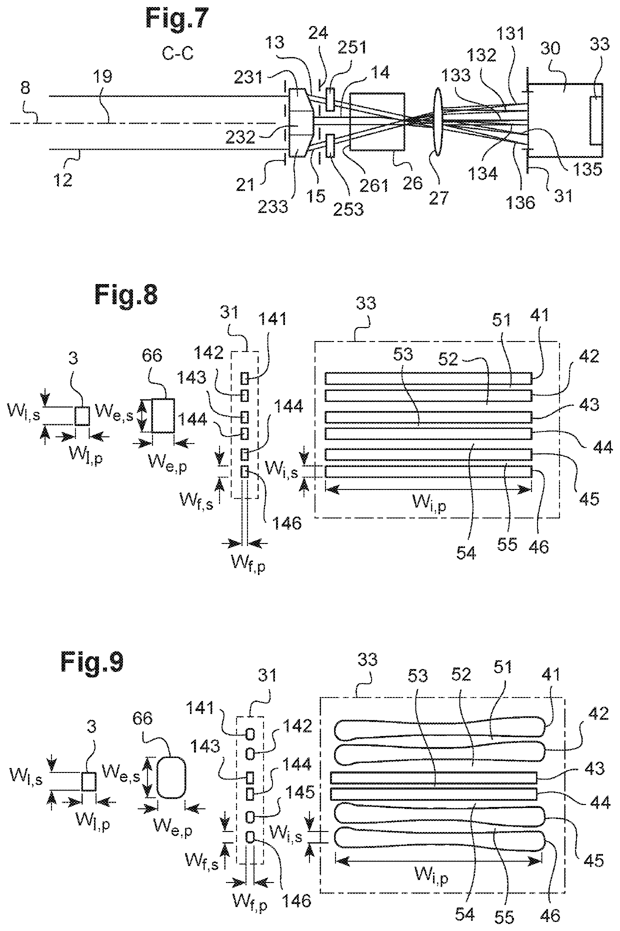
[0115]FIGS. 6 and 7 show an ellipsometer or scatterometer according to a The same signs of reference denote components or systems similar to those of FIGS. 1 to 5.

[0116]Similarly to the first embodiment, the illumination arm 50 includes a source diaphragm 3, an optical system 4 and a polarizer 5. However, unlike the first embodiment, the optical system 4 of the illumination arm 50 is arranged so as to illuminate the sample 6 with a polarized incident light beam 11 that is collimated and not focused on the sample 6. In the second embodiment, the polarized incident light beam 11 is a beam collimated on the sample corresponding to a planar wavefront. Moreover, in the second embodiment, the secondary light beam 12 formed by reflection, transmission or diffraction of the polarized incident light beam 11 on the sample 6 is also a collimated beam corresponding to a planar wavefront.

[0117]FIG. 7 schematically shows the detection arm 60 according to the second embodiment in a sectional plan...


PUM

PropertyMeasurementUnit
wavelength rangeaaaaaaaaaa
thicknessaaaaaaaaaa
thicknessaaaaaaaaaa

Abstract

Disclosed is an ellipsometer or scatterometer including a light source, a polarizer, an optical illumination system suitable for directing an incident polarized light beam towards a sample, a wavefront-division optical beam splitter arranged to receive a secondary light beam produced by reflection, transmission or diffraction, the wavefront-division optical beam splitter being oriented to form three collimated split beams, an optical polarization modification device and an optical polarization splitting device to form six angularly split beams, a detection system suitable for detecting the six split beams, and a processing system suitable for deducing therefrom an ellipsometric or scatterometric measurement.

Description

TECHNICAL FIELD TO WHICH THE INVENTION RELATES[0001]The present invention generally relates to the field of optical instruments for measuring materials and / or thin layers.[0002]More particularly, it relates to a spectroscopic or monochromatic ellipsometer or scatterometer and a spectroscopic or monochromatic ellipsometry or scatterometry method.[0003]It more particularly relates to a spectroscopic or monochromatic ellipsometer or scatterometer with a very high measurement rate.TECHNOLOGICAL BACK-GROUND[0004]A spectroscopic ellipsometer or scatterometer generally includes an illumination arm and a detection arm. The illumination arm comprises a wide spectral band light source and a polarizer configured to polarize a light beam incident on a sample with a determined angle of incidence (AOI). The detection arm receives a light beam formed by reflection or transmission, for an ellipsometer, and by diffraction for a scatterometer, of the beam incident on the sample, and comprises a polar...

Claims


Application Information

Patent Timeline
Patent Type & Authority Applications(United States)
IPC IPC(8): G01N21/21G02B27/10G02B5/30
CPCG01N21/211G01N2021/213G02B5/3025G02B27/1006G01N21/274G01N21/47G01N2021/4792
Inventor ACHER, OLIVIERPODZOROV, ALEXANDERNGUYEN, THANH-LIEMVILLIER, BRICEMELIZZI, GÉRALDINEGASTON, JEAN-PAUL
Owner HORIBA FRANCE SAS
Features
  • R&D
  • Intellectual Property
  • Life Sciences
  • Materials
  • Tech Scout
  • Unparalleled Data Quality
  • Higher Quality Content
  • 60% Fewer Hallucinations
Learn More