
Dual purpose position indicator

Active Publication Date: 2021-01-21
BAKER HUGHES OILFIELD OPERATIONS LLC
View PDF0 Cites 0 Cited by
  • Summary
  • Abstract
  • Description
  • Claims
  • Application Information

AI Technical Summary

Benefits of technology

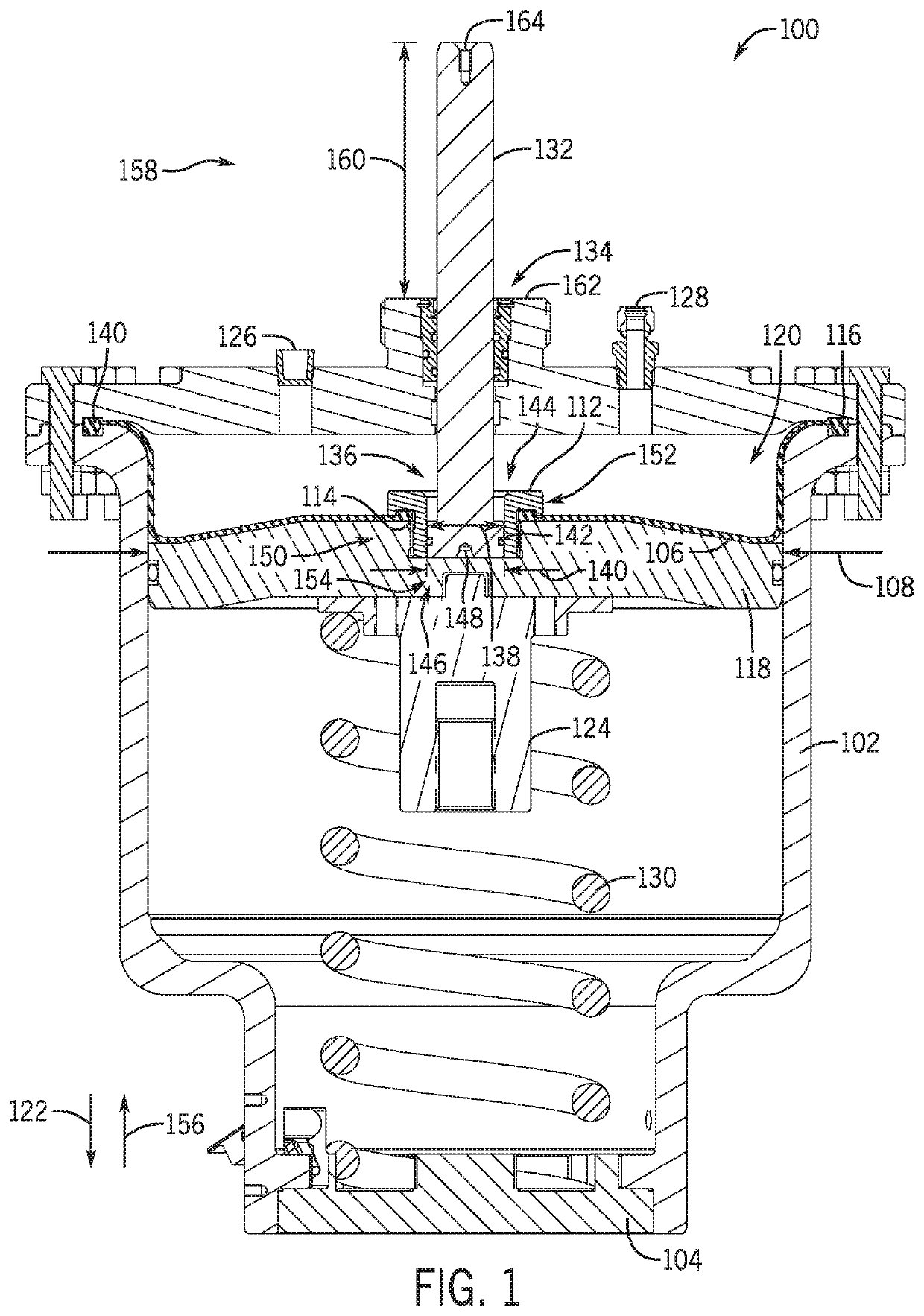
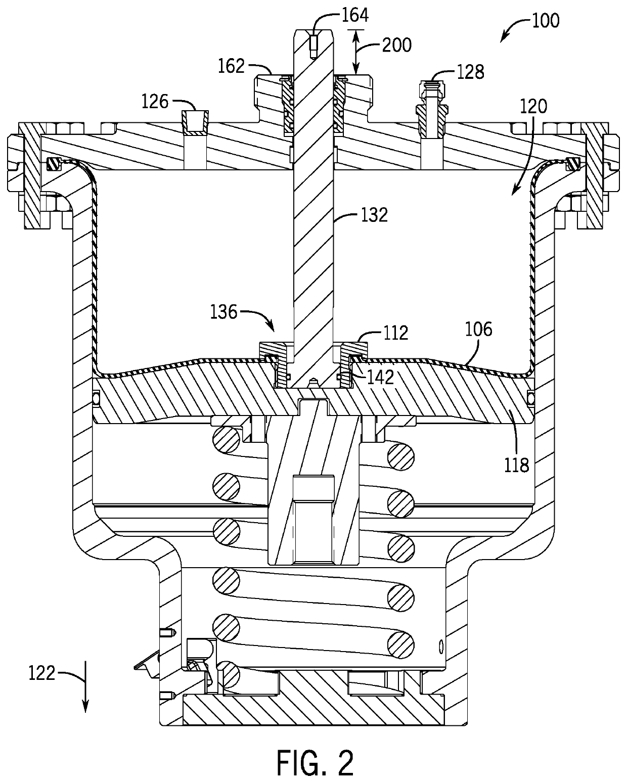
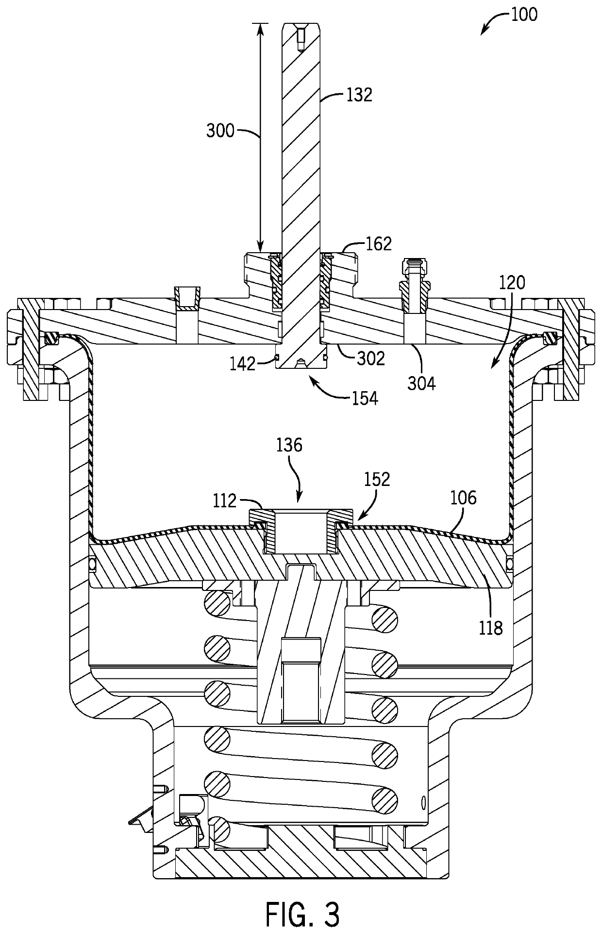
The patent text describes systems and methods for providing an indicator for a diaphragm actuator, which is used to move a valve between an open and closed position. The actuator includes a housing, a support plate, and a diaphragm. A visual position indicator (VPI) is also included, which includes an indicator rod that is secured to the support plate and extends through an opening in the actuator housing. The indicator rod is designed to release in response to a pressure from the working fluid acting at the bottom of the indicator rod. This release occurs when there is a leak point in the actuator that causes pressure to act on the indicator rod. The technical effect of this design is that it allows for a quick and easy way to identify leaks in the actuator, which can improve efficiency and prevent damage or injury.

Problems solved by technology

However, it may be difficult to inspect and detect leaks or tears in the diaphragm, and as a result, operation of the valve may be negatively impacted without an operator knowing until attempting to stroke the valve.

Method used


Image

  • Dual purpose position indicator
  • Dual purpose position indicator
  • Dual purpose position indicator

Examples


Embodiment Construction

[0020]The foregoing aspects, features and advantages of the present technology will be further appreciated when considered with reference to the following description of preferred embodiments and accompanying drawings, wherein like reference numerals represent like elements. In describing the preferred embodiments of the technology illustrated in the appended drawings, specific terminology will be used for the sake of clarity. The present technology, however, is not intended to be limited to the specific terms used, and it is to be understood that each specific term includes equivalents that operate in a similar manner to accomplish a similar purpose.

[0021]When introducing elements of various embodiments of the present invention, the articles “a,”“an,”“the,” and “said” are intended to mean that there are one or more of the elements. The terms “comprising,”“including,” and “having” are intended to be inclusive and mean that there may be additional elements other than the listed eleme...


PUM


Abstract

An actuator assembly for moving a valve between an open position and a closed position includes an actuator housing forming at least a portion of a chamber. The actuator assembly also includes a support plate arranged within the actuator housing. The actuator assembly further includes a diaphragm coupled to the actuator housing and the support plate, the diaphragm expanding and contracting in response to a working fluid within the chamber. The actuator assembly also includes an indicator rod extending through the chamber and out of the actuator housing, the indicator rod being removably coupled to the support plate, wherein the indicator rod is arranged within an opening formed in the support plate, the indicator rod secured to the support plate via a coupling mechanism that releases the indicator rod in response to a pressure from the working fluid between the diaphragm and the support plate.

Description

BACKGROUND OF THE DISCLOSURE1. Field of the Disclosure[0001]The present disclosure relates in general to valves for mineral recovery wells, and in particular to indicators regarding an operating condition of the valves.2. Brief Description of Related Art[0002]Valves used in hydrocarbon drilling and production operations can be operated by a variety of different actuators, such as pneumatic, piston, hydraulic, and the like. In operation, the actuator moves a stem linearly or rotationally, or both linearly and rotationally, to open or close the valve. The actuator may include a rod that extends to a cap, which further couples to a stem of the valve to translate motion from the actuator to the stem. Certain types of actuators may include bladders or diaphragms that move in response to pressure media, such as gas or other fluids, urging the diaphragm toward the valve body. The diaphragm is supported by a support plate. When the diaphragm is urged downward with the pressure media, it urg...

Claims


Application Information

Patent Timeline
IPC IPC(8): F16K37/00G01M3/28F16K31/126
CPCF16K37/0008F16K31/126G01M3/2876F16K31/1221F15B2211/864F15B15/10F15B15/2892F15B19/005F16K31/1262
Inventor CHOATE, JEREMY RYANMCEVOY, TRAVIS KYLECHEATHAM, LLOYD R.ADAMS, KEITH M.
Owner BAKER HUGHES OILFIELD OPERATIONS LLC
Learn More