Long flexible tubing element (variants)

a flexible tube and variable technology, applied in the field of long-diameter flexible tubes, can solve the problems of increasing the weight of multi-channel string due to deposited plastic, the need to cut through the solid plastic enclosure, and adversely affecting the tightness of stripper (annular seal) and blowout preventer equipment, so as to reduce the tensile and compressive load acting

Inactive Publication Date: 2021-01-21
UCT TECH LLC RU RU
View PDF0 Cites 0 Cited by
  • Summary
  • Abstract
  • Description
  • Claims
  • Application Information

AI Technical Summary

Benefits of technology

[0011]Therefore, it is the first aim of the present invention to provide several embodiments of umbilical flexible tubing element, which can have various diameters, cross-sections, and/or configurations, composed from basic pairs of isolated channels that are produced from a single strip or several strips and have one or more flanges and/or partition ...

Problems solved by technology

One disadvantage of above-mentioned multi-channel umbilical coil tubing consists in increased weight of the multi-channel string due to deposited plastic.
Another disadvantage is necessity to cut through the solid plastic enclosure in order to repair or replace a damaged electric line section (breakdown, earth fault, etc.) or fiber-optic or capillary line section (disrupted channel) followed by re-welding of plastic.
In addition, deep and long scratches or abrasions on outer surface of plastic adversely affect the tightness of stripper (annular seal) and blowout preventer equipment.
One disadvantage of above-mentioned multi-channel coil tubing consists in increased weight of the multi-channel string due to deposited plastic.
In addition, deep and long scratches or abrasions on outer surface of plastic adversely affect the tightness of stripper (annular seal) and blowout preventer equipment.
Principal disadvantage of above mentioned configurable multi-channel umbilical flexible tubing is stepwise change in cross-section geometry of the string in the place of permanent weld clamps installation, which impairs integrity of the multi...

Method used


Image

  • Long flexible tubing element (variants)
  • Long flexible tubing element (variants)
  • Long flexible tubing element (variants)

Examples


first embodiment

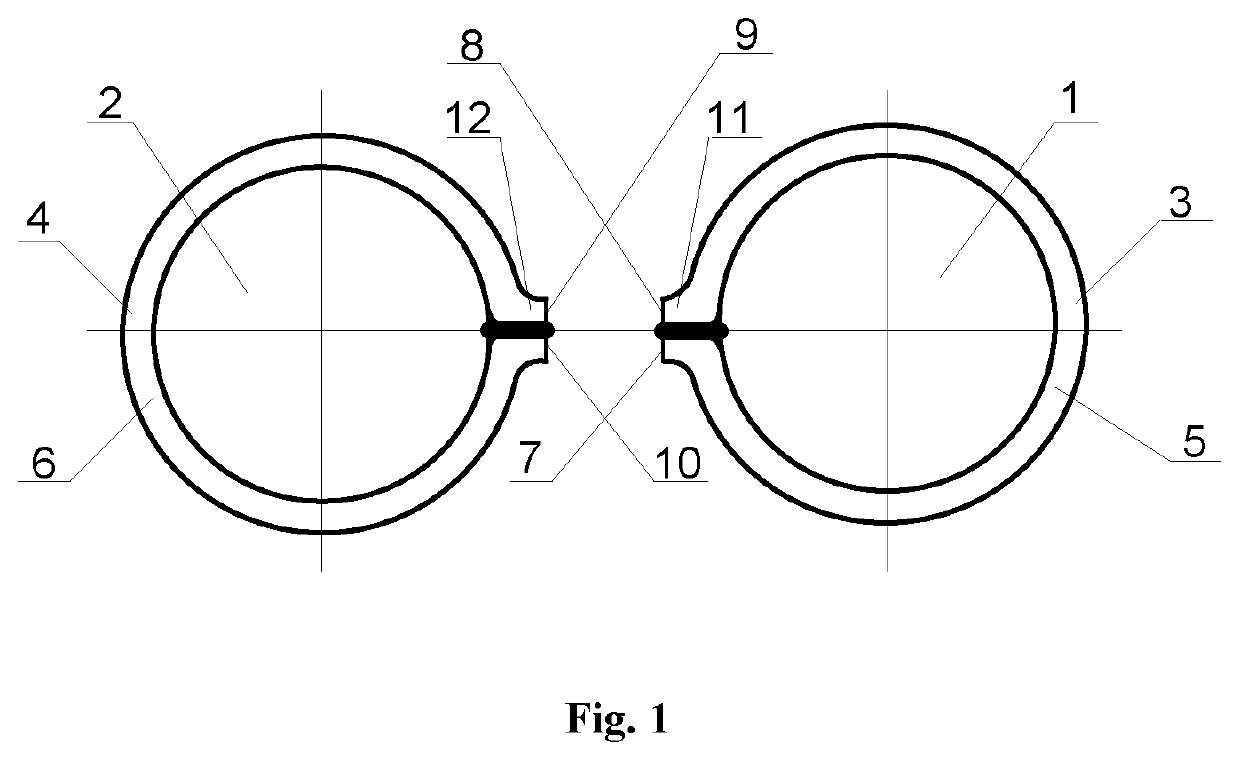
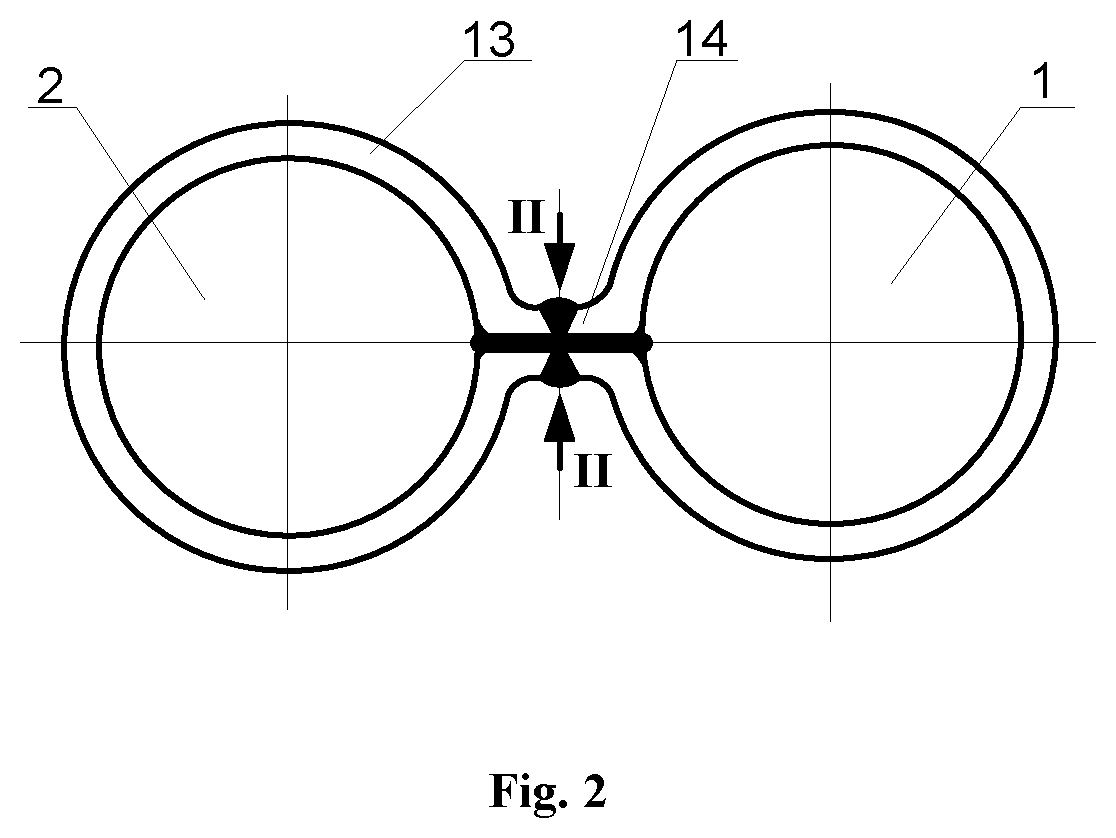
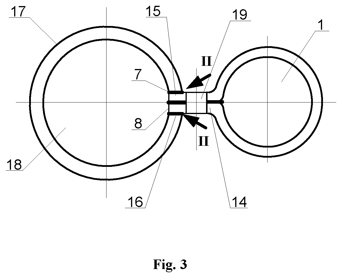
[0046 of basic pair of isolated channels 1 and 2 for the umbilical flexible tubing element, as FIG. 1 shows, is manufactured by initial shaping two strips 3 and 4 by series of rollers from their centers to form walls 5 and 6 of isolated channels 1 and 2 with pairwise aligning ends 7 and 8 vs. 9 and 10 of the inverted longitudinal edges of strips 3 and 4 along two planes faced one against another from both sides of the central plane A-A, and subsequent welding of contacting surfaces of the ends 7 and 8 vs. 9 and 10 of inverted longitudinal edges with each other to form the basic pair of isolated channels 1 and 2 with edge flanges 11 and 12, respectively. Then ends of edge flanges 11 and 12 of isolated channels 1 and 2 are welded with each other to form the basic pair 10 of isolated channels 1 and 2 interconnected by a connecting partition 14 (FIG. 2). As a special case of above embodiment, a second isolated channel 18 (FIG. 3) of basic pair 10 can be formed by extending the welded co...

second embodiment

[0047 of basic pair 20 of isolated channels 21 and 22 for the umbilical flexible tubing element, as FIG. 4 shows, is manufactured by initial shaping two strips 23 and 24 by series of rollers from their centers to form shaped flanges 25 and 33 in the form of longitudinal folds with welded interior. Then lateral parts of strip 23 are shaped with facing ends 26 and 27 of inverted longitudinal edges of strip 23 one against another from both sides of the central plane B-B with subsequent welding contacting surfaces of the ends 26 and 27 of inverted longitudinal edges with each other to form the isolated channel 21 with edge flange 28. The lateral parts of another strip 24 are similarly shaped with facing ends 29 and 30 of inverted longitudinal edges of strip 24 one against another from both sides of the central plane B-B, and subsequent welding the contacting surfaces of the ends 29 and 30 of inverted longitudinal edges with each other to form basic isolated channel 22 with edge flange 3...

third embodiment

[0048 of basic pair 40 of isolated channels 41 and 42 for the umbilical flexible tubing element, as FIGS. 9 and 10 show, is manufactured by initial shaping a single strip 43 from center to form shaped flange 44 in the form of longitudinal fold with welded interior. Then the remaining parts of the strip 43 are shaped to form walls of the first isolated channel 41 with subsequent welding the channel 41 wall joints with each other along contacting surfaces to form a connecting partition 45 (FIG. 9). Thereafter, remaining parts of strip 43 are shaped with facing ends 46 and 47 of inverted longitudinal edges of strip 43 one against another from both sides of the central plane C-C, with subsequent welding the contacting surfaces of the ends 46 and 47 of inverted longitudinal edges with each other to form the isolated channel 42 with edge flange 48 (FIG. 10). As a special case of the third embodiment, it is possible to manufacture a four-channel embodiment of long umbilical flexible tubing...


PUM

PropertyMeasurementUnit
Weightaaaaaaaaaa
Longitudeaaaaaaaaaa
Flexibilityaaaaaaaaaa

Abstract

The invention relates to long-dimensional flexible tubes (coiled tubing). There are several variants of the proposed basic pairs of an umbilical coiled tubing and include means of their production with multi-stage sequential shaping process of one or multiple strips at an estimated geometry, and where isolated channels, partitions and flanges are formed during this process. If required, longitudinal butts of an additional shaped longitude strips can be welded to them to form additional hydraulic channels of the umbilical coiled tubing which can be reeled up to a drum. Other types of service channels (electric, fiber-optic, capillary etc.) or standard coiled tubing can be placed inside or outside channels in the form of a service channels tape. Flanges located beyond the outside dimensions of an umbilical coiled tubing may have a wave-type of form. Connecting partitions may have holes intended for fingers of injector, for elevator, for service channels tape. Flanges and partition holes are weight-carrying members of umbilical coiled tubing. Welding seams, flanges, centers of a closed channels and partitions are located, mainly, on the middle line of an umbilical coiled tubing's cross-section. The umbilical coiled tubing makes it possible to significantly increase possibilities of coiled tubing units in technological operations as well as in artificial lift methods due to its multi-channel design and, consequently, multifunctionality.

Description

FIELD OF THE INVENTION[0001]The invention relates to long-dimensional flexible tubes (coiled tubing or lengthy flexible tubing), more specifically, reel spoolable coiled tubing.BACKGROUND[0002]As practice of coiled tubing application in wells shows, it is reasonable to have multi-channel umbilical coiled tubing with various diameters, designs, and auxiliary service channels for implementation of many technological operations inside boreholes as well as reservoir fluid lifting using different artificiall lift methods.[0003]A multi-channel umbilical coiled tubing is known comprising several hydraulic and electrical channels, which are (encapsulated) enclosed together in a single fused shell extruded from a polymer material with two flat surfaces for easy spooling. The extruded enclosure from polymeric material around the hydraulic and electrical channels forms a single multi-channel string in the shape of a long-dimensional flexible tape, which provides good protection for the hydraul...

Claims


Application Information

Patent Timeline
IPC IPC(8): F16L11/22F16L11/04
CPCF16L11/22F16L11/042B21C37/0818B21C37/151B23K31/027F16L11/15E21B17/20F16L11/16
Inventor GABDULLIN, RIVENER MUSAVIROVICH
Owner UCT TECH LLC RU RU
Why Eureka
Try Eureka