
Carotid artery blood pressure detecting device

a detection device and carotid artery technology, applied in the field of carotid artery blood pressure detection devices, can solve the problems of allergic reactions, time-consuming, and time-consuming foregoing clinical methods for assessing carotid stenosis, and achieve the effect of reducing the examination tim

Active Publication Date: 2021-01-28
LIN SHIMING +1
View PDF4 Cites 0 Cited by
  • Summary
  • Abstract
  • Description
  • Claims
  • Application Information

AI Technical Summary

Benefits of technology

The patent text is about a new method for quickly detecting carotid stenosis, which can lead to strokes and dementia. The current methods are time-consuming and have limitations. The invention uses sensors to detect the pressure of the carotid arteries, allowing for a faster screening test. This can be particularly useful for patients who have already had a stroke or are at risk of cardiovascular disease. The method is non-invasive and does not require the use of contrast agents or radiation.

Problems solved by technology

Methods conventionally used to diagnose carotid stenosis and determine the CBV include DSA, MRA, Doppler ultrasound scanning, etc. of the carotid arteries, but the foregoing clinical methods for assessing carotid stenosis have their respective limitations and are time-consuming.
Angiographic methods such as DSA and MRA take even longer time and entail risks associated with their invasive procedures and the use of contrast agents, which may cause allergic reactions.
Computed tomography angiography (CTA), which has become more and more common in recent years, involves risks related to radiation as well as contrast agents.

Method used


Image

  • Carotid artery blood pressure detecting device
  • Carotid artery blood pressure detecting device
  • Carotid artery blood pressure detecting device

Examples


first embodiment

[0047]Reference is now made to FIG. 4 for a schematic drawing that shows a state of use of the present invention. As shown in FIG. 4, the carotid blood pressure detection device according to this embodiment includes an adhesive patch 20, and the adhesive patch 20 is provided with the first sensing unit 11 and the second sensing unit 12. The first sensing unit 11 and the second sensing unit 12 are provided on the adhesive patch 20 in a symmetric fashion and are properly spaced apart so as correspond respectively to the first position and the second position of a subject's carotid arteries when adhesively attached to the subject's neck. In one preferred embodiment, the first sensing unit 11 and the second sensing unit 12 are fixedly connected to the adhesive patch 20 and are therefore spaced apart by a fixed distance. In another preferred embodiment, the adhesive patch 20 is provided with an adjustment enabling structure (e.g., a groove or rail) so that the distance between the first ...

second embodiment

[0048]FIG. 5 schematically shows a state of use of the present invention. As shown in FIG. 5, the carotid blood pressure detection device according to this embodiment includes an adhesive patch 30, on which the first sensing unit 11 and the second sensing unit 12 are provided. The adhesive patch 30 is further provided with a thyroid cartilage locating hole 31. The first sensing unit 11 and the second sensing unit 12 are provided on one side of the thyroid cartilage locating hole31 and are properly spaced apart so as to correspond respectively to the first position and the second position of a subject's carotid arteries when adhesively attached to the subject's neck. In one preferred embodiment, the first sensing unit 11 and the second sensing unit 12 are fixedly connected to the adhesive patch 30 and are therefore spaced apart by a fixed distance. In another preferred embodiment, the adhesive patch 30 is provided with an adjustment enabling structure (e.g., a groove or rail) so that...

third embodiment

[0050]FIG. 6 schematically shows a state of use of the present invention. As shown in FIG. 6, the carotid blood pressure detection device according to this embodiment includes an adhesive patch 40, on which the first sensing unit 11 and the second sensing unit 12 are provided. The adhesive patch 40 is further provided with a thyroid cartilage locating mark 41. The first sensing unit 11 and the second sensing unit 12 are provided on one side of the thyroid cartilage locating mark 41 and are properly spaced apart so as to correspond respectively to the first position and the second position of a subject's carotid arteries when adhesively attached to the subject's neck. In one preferred embodiment, the first sensing unit 11 and the second sensing unit 12 are fixedly connected to the adhesive patch 40 and are therefore spaced apart by a fixed distance. In another preferred embodiment, the adhesive patch 40 is provided with an adjustment enabling structure (e.g., a groove or rail) so tha...


PUM


Abstract

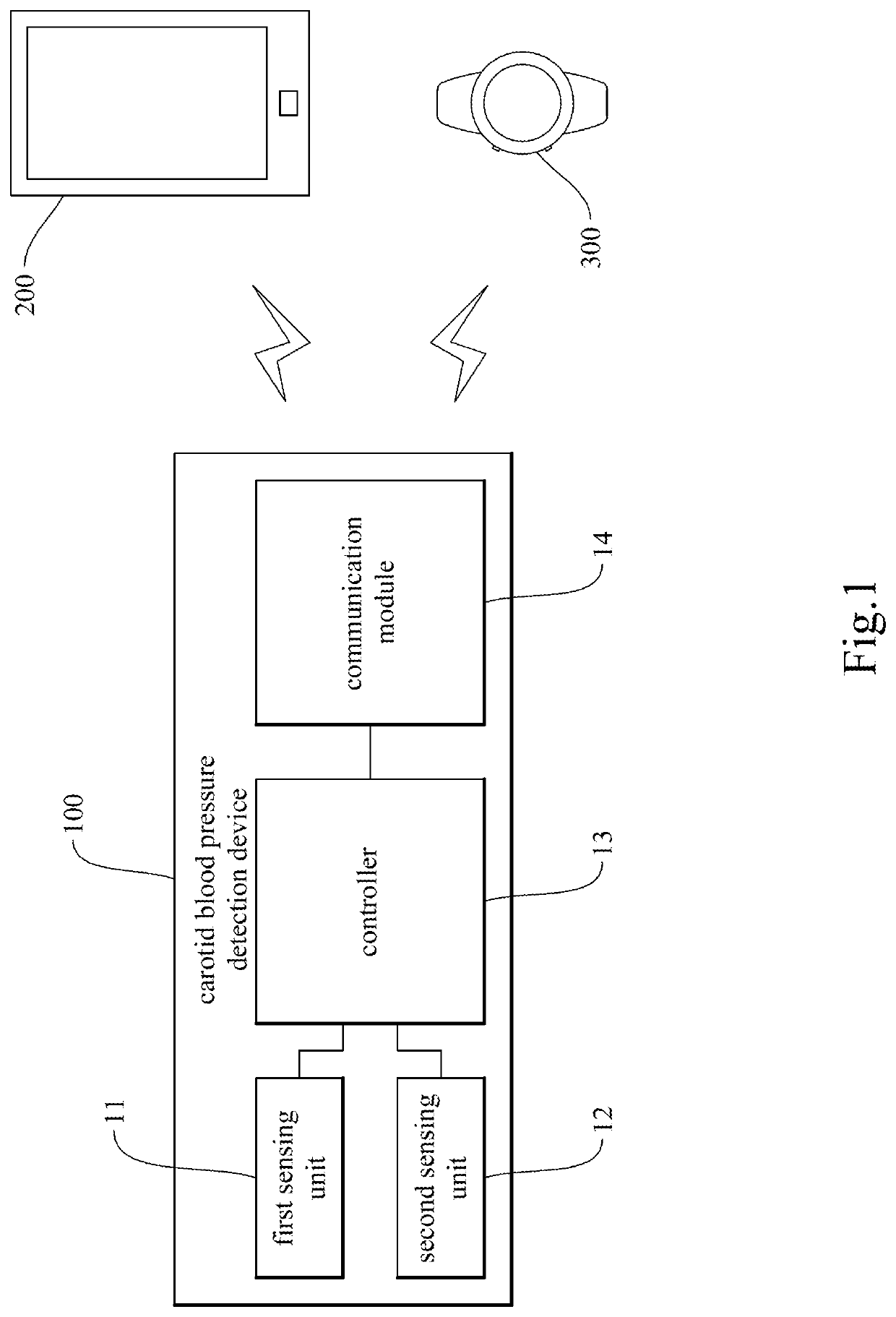
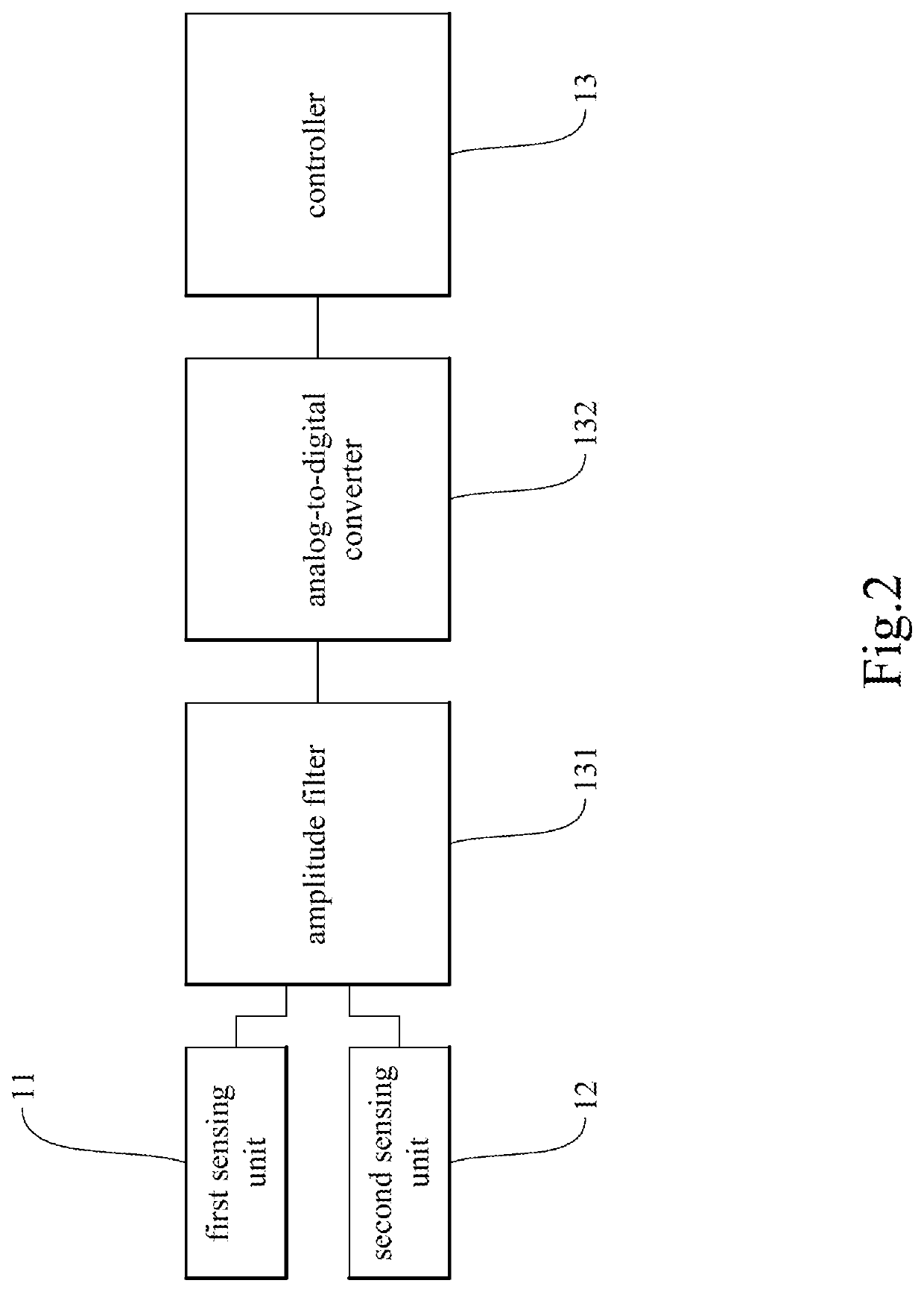
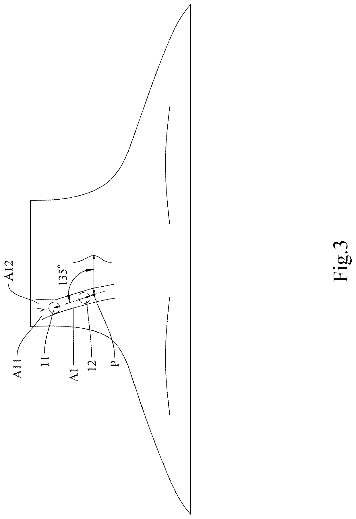
The present invention provides a carotid blood pressure detection device, comprising: a first sensing unit, a second sensing unit, and a controller connected or coupled to the first sensing unit and the second sensing unit. The first sensing unit is disposed on a subject's neck and adjacent to a first position of the subject's carotid arteries. The second sensing unit is disposed on the subject's neck and adjacent to a second position of the subject's carotid arteries. The controller derives a mean arterial pressure of a section of the subject's carotid arteries that lies between the first position and the second position of the subject's carotid arteries from pulse wave data measured and obtained by the first sensing unit and pulse wave data measured and obtained by the second sensing unit.

Description

BACKGROUND OF THE INVENTION1. Technical Field[0001]The present invention relates to a blood pressure detection device, and particularly to a carotid blood pressure detection device for detecting carotid blood pressure.2. Description of Related Art[0002]The carotid arteries are the main source arteries that supply blood to the brain but are also the predilection sites for atherosclerosis. Carotid arteriosclerosis may lead to brain ischemia or even a severe stroke and is therefore an important risk factor of cerebrovascular disease. Moreover, the presence and degree of carotid arteriosclerosis may reflect to a certain extent the presence and degree of arteriosclerosis of the other major arteries. The carotid arteries are shallow, easy to detect, and hence a clinical window through which to discover arteriosclerosis.[0003]A stroke is a cerebrovascular disease that stems from insufficient blood supply to the brain and that causes damage to the central nervous system, occurring typically...

Claims


Application Information

Patent Timeline
Patent Type & Authority Applications(United States)
IPC IPC(8): A61B5/021A61B5/00A61B5/05A61B8/04
CPCA61B5/02125A61B5/6833A61B5/684A61B5/02416A61B5/0507A61B8/04A61B5/002A61B5/02007A61B5/14552A61B5/6824A61B5/6823A61B5/6822A61B5/282A61B5/02108A61B5/02438A61B5/0245A61B2562/0247A61B5/0004A61B5/7275A61B7/04
Inventor LIN, SHIMING
Owner LIN SHIMING
Learn More