Motor control system

a technology of motor control and control system, which is applied in the direction of electric generator control, dynamo-electric converter control, dynamo-electric gear control, etc., can solve the problems of disadvantageous movable objects, large equipment, and small motors, and achieves the effect of reducing cost and weight, avoiding enlargement of motors, and improving fuel economy

Active Publication Date: 2021-02-04
MAZDA MOTOR CORP
View PDF0 Cites 2 Cited by
  • Summary
  • Abstract
  • Description
  • Claims
  • Application Information

AI Technical Summary

Benefits of technology

[0025]In a so-called hybrid vehicle, the drive motor is driven in cooperation with the engine. Thus, by combining both of the output, the hybrid vehicle can further favorably be driven. In the case where the rated voltage of the battery is equal to or lower than 50 V, an advanced insulation measure does not have to be taken, which reduces co

Problems solved by technology

In general, many motors are small-sized and produce low output.
However, as recognized by the present inv

Method used


Image

  • Motor control system
  • Motor control system
  • Motor control system

Examples


Embodiment Construction

[0035]A description will hereinafter be made on an embodiment of the disclosed technique with reference to the drawings. The following description is essentially and merely illustrative and thus has no intention to limit the present invention, application subjects thereof, and application thereof.

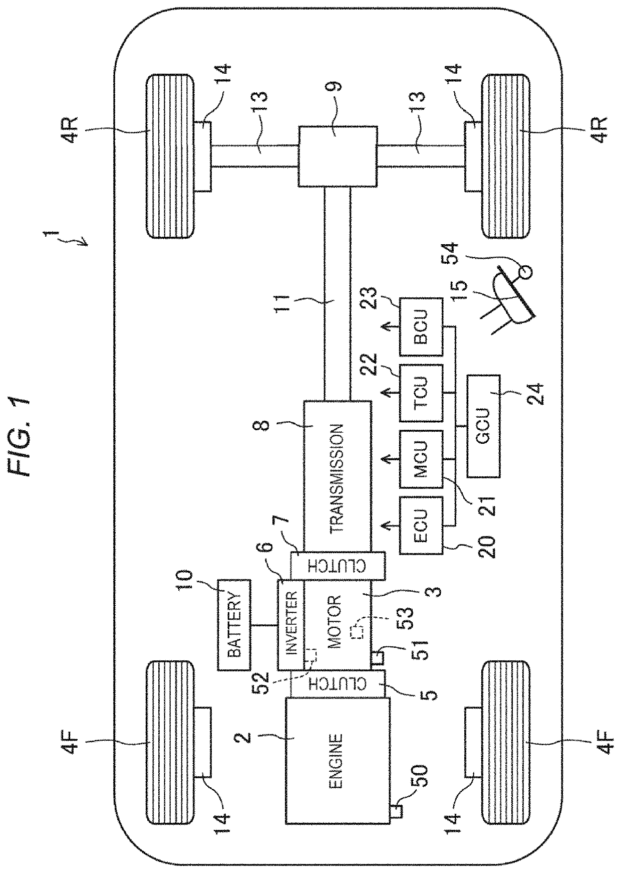
[0036]FIG. 1 illustrates a four-wheeled automobile 1 (an example of the movable object) to which the disclosed technique is applied. This automobile 1 is a hybrid vehicle. An engine 2 and a drive motor 3 are mounted as drive sources of the automobile 1. These cooperatively drive, of four wheels 4F, 4F, 4R, 4R, two wheels (drive wheels 4R) that are located in a bilaterally-symmetrical manner. In this way, the automobile 1 moves (travels).

[0037]In a case of this automobile 1, the engine 2 is arranged in a front portion of a body, and the drive wheels 4R are arranged in a rear portion of the body. That is, this automobile 1 is a so-called FR vehicle. Furthermore, in the case of this automobile...


PUM


Abstract

A motor control system configured to be mounted to a movable object that moves by using a drive motor, the motor control system comprising: a sensor configured to detect an output requested to drive the movable object; a battery configured to supply electric power to the drive motor; and circuitry configured to control the drive motor such that a requested amount of rotary power of the drive motor is output in a specified output range, the requested amount of the rotary power of the drive motor being set on the basis of a detection value of the output sensor.

Description

CROSS-REFERENCE TO RELATED APPLICATION[0001]The present application claims priority to JP 2019-141549, filed Jul. 31, 2019, the entire contents of which are incorporated herein by reference.TECHNICAL FIELD[0002]The disclosed technique relates to a motor control system mounted on a movable object that moves by using a drive motor.BACKGROUND ART[0003]A motor is a device (an electric motor) that converts electrical energy into kinetic energy. The motor can easily be controlled, and thus is used in various fields such as a field of home appliances. In general, many motors are small-sized and produce low output. Meanwhile, relatively large-sized, high-output motors (drive motors) for driving a train, an elevator, and the like are also available. In a power plant and the like, the motor is also used as a generator.[0004]In recent years, use of the drive motors for electric vehicles, hybrid vehicles, and the like has been increased. For example, in JP-A-2014-231290 (Patent document 1), a h...

Claims


Application Information

Patent Timeline
IPC IPC(8): H02P21/22H02P27/12B60L15/20
CPCH02P21/22B60W2540/10B60L15/20H02P27/12H02P23/26H02P27/08H02P25/02H02K1/2753H02K1/146H02K2213/09B60L15/025B60L2220/14B60L2240/423B60L2240/429H02P21/0089Y02T10/64Y02T10/72
Inventor ITASAKA, NAOKIKABASHIMA, HISAYUKI
Owner MAZDA MOTOR CORP
Why Eureka
Try Eureka