Ultrasound imaging apparatus and method

Pending Publication Date: 2021-02-11
KONINKLJIJKE PHILIPS NV
View PDF0 Cites 1 Cited by
  • Summary
  • Abstract
  • Description
  • Claims
  • Application Information

AI Technical Summary

Benefits of technology

This patent describes an apparatus that can image large organs or organs with motion from multiple angles simultaneously. By repeating a scan sequence and combining image data from different probes, the apparatus can create stitched or fused images that provide a more complete view of the organ. This improves image quality and enhances the surgeon's ability to diagnose or treat the organ.

Problems solved by technology

Most of the time using a single ultrasound transducer it is difficult to see tissues or organs underlying an anechoic structure such as bone, so a lot of clinically relevant information remains hidden.
The ultrasound signals returning after these reverberations are incorrectly viewed as being returned from deeper structures, since it took them longer to return to the probe.
Using a single probe for scanning the patient, it is not easy to differentiate between normal tissue and artefacts when looking at the echo images.
Another problem found during diagnosis using a single probe is in the scanning of large organs such as the lung, placenta and kidney, and organs having motion such as the heart and the foetus.

Method used


Image

  • Ultrasound imaging apparatus and method
  • Ultrasound imaging apparatus and method
  • Ultrasound imaging apparatus and method

Examples


first embodiment

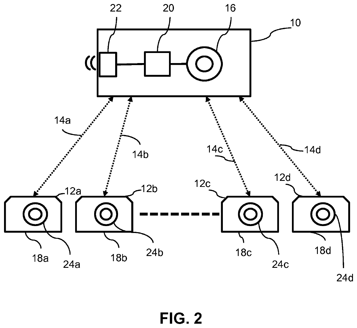
[0067]In the first embodiment described with reference to FIG. 2, a master control unit 10 communicates with slave probes 12a, 12b, 12c and 12d, and optionally additional similar probes (not shown), over paths represented by lines 14a, 14b, 14c and 14d. A global clock 16 in the control unit 10 is provided, and this may be set by an external global clock (not shown), for example by a server over the Internet, or by a relay message from another control unit. Internal local clocks 18a, 18b, 18c and 18d in the respective connected probes are synchronized from the global clock over the same paths of communication 14a-14d.

[0068]The control unit comprises a data processor 20 running an application which controls the whole system of master and slaves, and which communicates through a communications unit 22 with the probes and with external networks such as other control units, hospital systems and the Internet. The control unit 10 sends beamforming control commands to the probes. It also c...

third embodiment

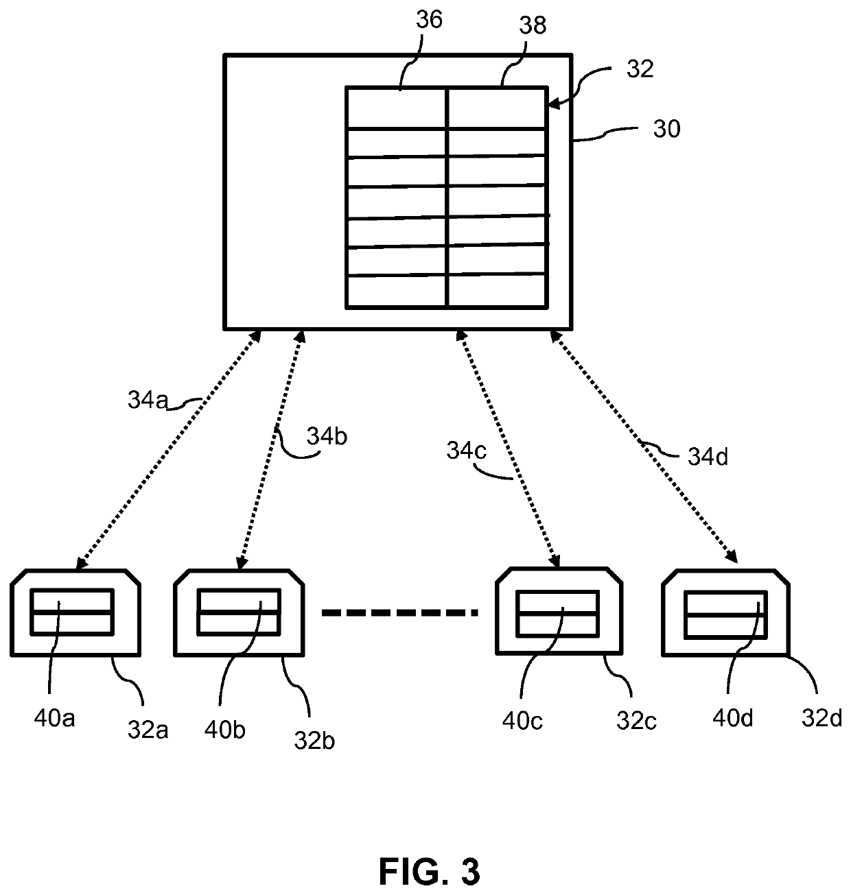
[0073]A third embodiment will now be described with reference to FIG. 4. This system is similar to that of FIG. 3, except that inter-probe communications are used for sequencing the probes. A register 52 in the master control unit 50 stores the triggering sequence of the connected probes 32a-32d. Each probe stores its own scan state, and also the identity of the probe that is the next in the firing sequence. Thus each probe can communicate with at least one other probe, and in most cases two other probes, and their communication paths are shown as 54, 56, 58, 60 and 62 in the drawing. As with the other embodiments, any number of probes may be used in the sequence. Beamforming begins with the first probe in the probe sequence set by the control unit 50 as master. The control unit 1 sends a command to the first probe 40a to initiate its scan, and also a signal indicative of the next probe, probe 32b, in the sequence. Instead of the identity of the probe, the signal could contain the I...


PUM


Abstract

Ultrasound imaging apparatus for imaging a region of interest in a subject comprises a plurality of separate ultrasonic probes (2a-2c) each having at least one transducer (72) for transmitting and receiving ultrasonic waves and a communications unit. A control unit (1) controls the probes to coordinate their operation in sequence, and obtains ultrasonic images from the probes for generating a display of those images together in real time simultaneously. The control unit transmits control signals to at least one of the probes, and each probe receives control signals from the control unit and / or from an adjacent one of the probes. The control signals cause the probes to execute a scan sequentially in a predetermined probe sequence which is usually repeated, and the control unit generates a display by combining the image data from the probes.

Description

FIELD OF THE INVENTION[0001]This invention relates to ultrasound imaging, especially medical imaging of the human body.BACKGROUND OF THE INVENTION[0002]Currently most medical ultrasound machines use a single transducer, also referred to as a probe, for patient diagnosis. The transducer transmits ultrasound waves and captures the reflected echo, typically using an array of piezoelectric elements. The echoes are subsequently converted to images for the final rendering to generate display data. The reflected echo intensity depends upon the echogenicity of the scanned tissue, organs or any structure in the region of interest. Depending upon the echogenicity, the structure could be hyperechoic (white on the display screen), hypoechoic (grey on the screen) or anechoic (black on the screen). Most of the time using a single ultrasound transducer it is difficult to see tissues or organs underlying an anechoic structure such as bone, so a lot of clinically relevant information remains hidden....

Claims


Application Information

Patent Timeline
IPC IPC(8): A61B8/00A61B8/08
CPCA61B8/4477A61B8/5207A61B8/466A61B8/4472A61B8/0841A61B8/54A61B8/14A61B8/5253
Inventor ODUNGATTU THODIYIL, ANUMODSHETTIGAR, SRIKANTH
Owner KONINKLJIJKE PHILIPS NV
Why Eureka
Try Eureka