Orbital welding system and method

a welding system and orbital technology, applied in the direction of soldering devices, manufacturing tools, auxillary welding devices, etc., can solve the problems of complex process, high labor intensity and high cost of using brazing materials in this manner, and achieve faster welding and more reliable welds

Inactive Publication Date: 2021-02-25
CRITICAL SYST
View PDF0 Cites 4 Cited by
  • Summary
  • Abstract
  • Description
  • Claims
  • Application Information

AI Technical Summary

Benefits of technology

[0004]Embodiments described herein are directed to systems, methods, and apparatuses for performing homogeneous, full-penetration orbital welds. These welds may be performed faster and result in more reliable welds than previous brazing systems. In one embodiment, an orbital welding system described herein includes a controller, a shielding gas supply system that supplies shielding gas to an orbital welding tool or weld head, an electrical supply system that supplies an electrical current to the orbital welding tool, and the c

Problems solved by technology

As such, the brazing process, once completed, is prone to leaks.
Moreover, using brazing materials in this manner is often complicated and typically requires specific skills.
This process is thu

Method used


Image

  • Orbital welding system and method
  • Orbital welding system and method
  • Orbital welding system and method

Examples


Embodiment Construction

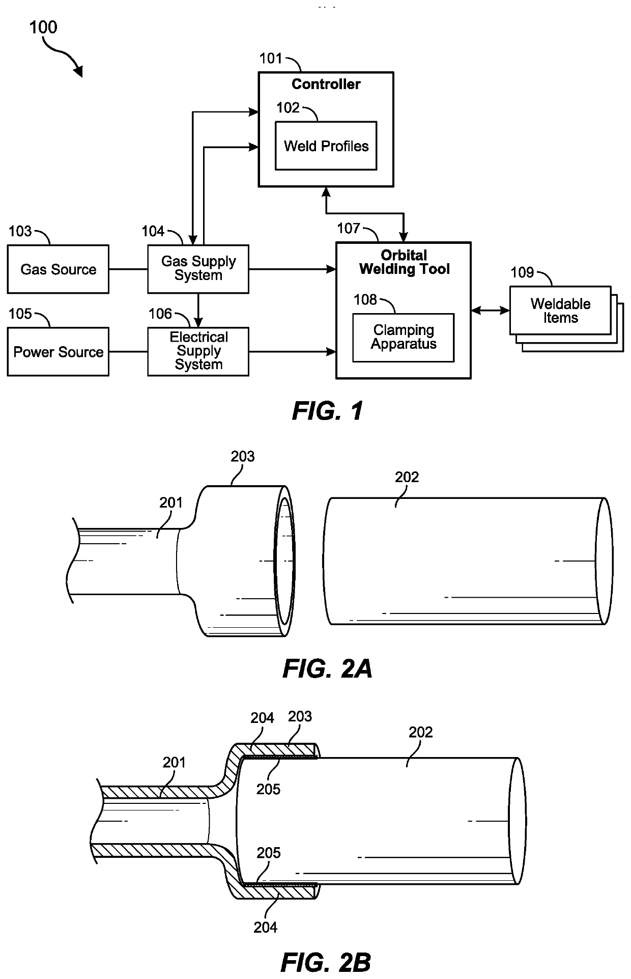
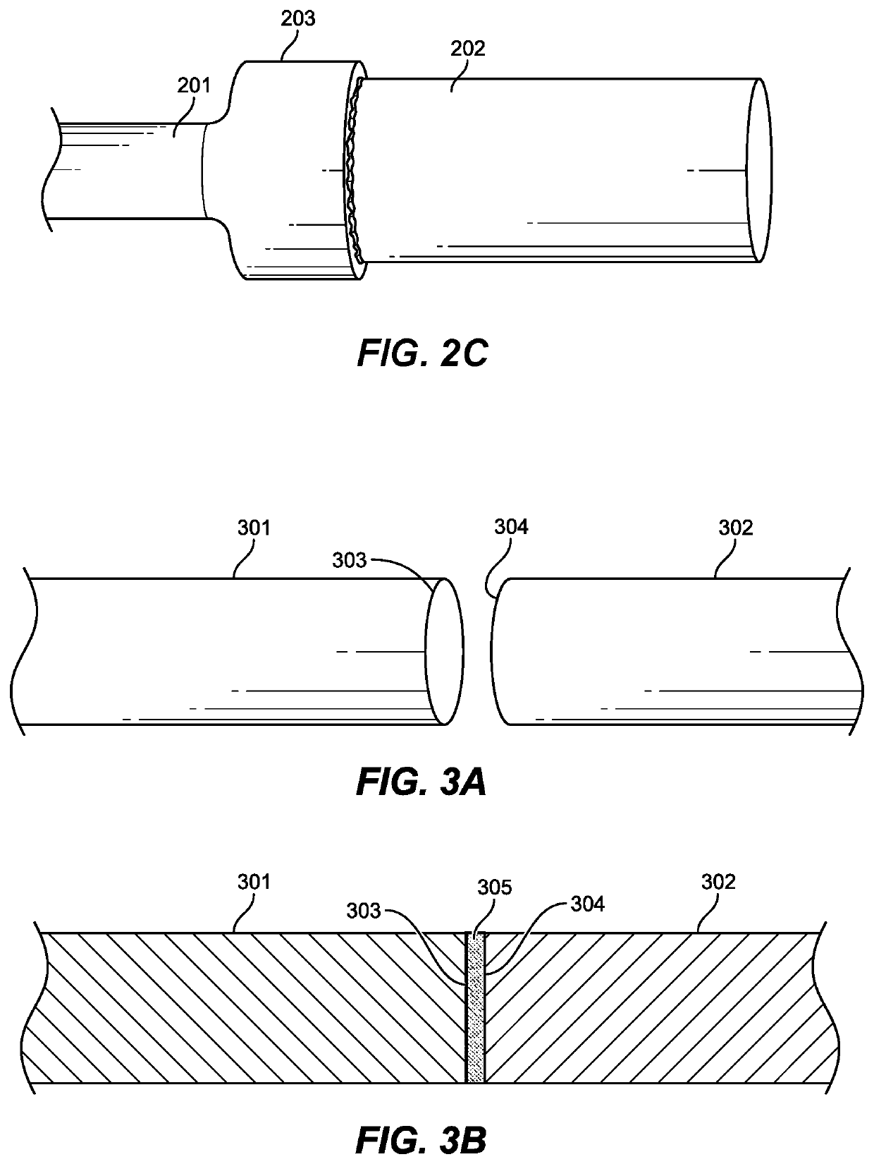
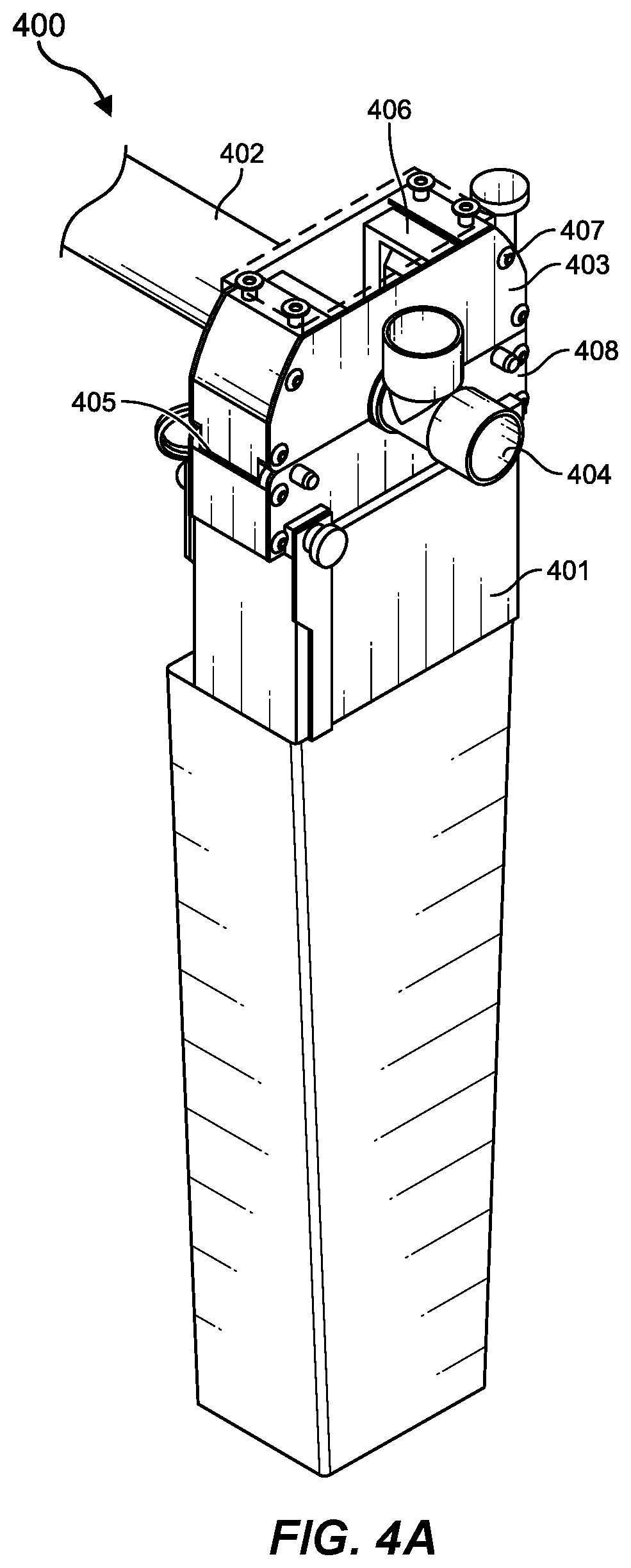
[0023]The embodiments described herein include systems and methods of using an orbital welding device, as well as methods for manufacturing an orbital welding device. The orbital welding system may include a system controller that applies a weld at specified intervals or at specified amperages, and using specified shielding gases or gas ratios. The orbital welding system may also include an orbital welding tool configured to weld two or more items together. In some cases, the two or more items may be two ends of a pipe or socket joint that are orbital welded together using a homogeneous, full-penetration weld. The full-penetration weld may penetrate through to an inner layer of the innermost surface so as to avoid leakage. The orbital welding system may also include a gas supply system that supplies various shielding gases to the orbital welding tool. Methods of using the orbital welding system may include welding pipes, tubes, and socket or butt to butt weld fittings with full pene...


PUM

PropertyMeasurementUnit
Fractionaaaaaaaaaa
Fractionaaaaaaaaaa
Fractionaaaaaaaaaa

Abstract

Embodiments are directed to an orbital welding system, including customized orbital weld head fixtures, and computer-controlled programs for performing homogeneous orbital welds. In one scenario, an orbital welding system includes a controller, a shield gas supply system that supplies gases to an orbital welding tool, an electrical supply system that supplies an electrical current to the orbital welding tool, and the orbital welding tool, which includes a welding electrode that is configured to weld two or more items together using the supplied electrical current and the gases supplied by the gas supply system. The controller generates control signals that direct the orbital welding tool, the electrical supply system, and the gas supply system to homogeneously orbital weld the at least two items together, so that the at least two items are homogeneously welded together without using a filler material. Various other methods, systems, and apparatuses are also described.

Description

CROSS-REFERENCE TO RELATED APPLICATIONS[0001]This application claims priority to and the benefit of U.S. Provisional Patent Application Ser. No. 62 / 889,013, entitled “Orbital Welding System and Method,” filed on Aug. 19, 2019, which application is incorporated by reference herein in its entirety.BACKGROUND[0002]When pipes or other similar structures need to be welded, a variety of different techniques may be used to form a weld around the pipe. These techniques often include soldering or brazing in which a filler material (e.g., a brazing rod) is used to bind two pieces of pipe together. When welding tube or pipe, specifically those that use socket joints, the filler material penetrates the outer edge of the pipe, but does not penetrate the inner edge of the pipe that is being fitted. As such, the brazing process, once completed, is prone to leaks.[0003]Moreover, using brazing materials in this manner is often complicated and typically requires specific skills. In some cases, brazin...

Claims


Application Information

Patent Timeline
IPC IPC(8): B23K9/095B23K9/028B23K9/16
CPCB23K9/0953B23K9/1006B23K9/16B23K9/0286B23K37/0533B23K9/167B23K9/0956B23K2101/06
Inventor JONES, THEODORE JVORRARO, III, RALPHDANNER, II, RICHARD
Owner CRITICAL SYST
Why Eureka
Try Eureka