Fast detection of secondary objects that may intersect the trajectory of a moving primary object

a secondary object and detection technology, applied in the field of fast detection of secondary objects, can solve the problems of large percentage of accidents occurring and taking too long

Pending Publication Date: 2021-02-25
PROPHESEE SA +1
View PDF4 Cites 18 Cited by
  • Summary
  • Abstract
  • Description
  • Claims
  • Application Information

AI Technical Summary

Benefits of technology

The inventors found that the motion of a primary object triggers a large number of events, which can be irrelevant for the task at hand. By identifying and focusing on the events caused by the motion of a secondary object, the system can safely disregard the irrelevant events and reduce the likelihood of false detections. Additionally, the invention provides a second embodiment where the light-sensitive area includes event-based pixels and image pixels in constant ratio, which allows for both the acquisition of events and images at the same spatial resolution, without requiring coordinate translation or scaling.

Problems solved by technology

An analysis of past road accidents has revealed that a large percentage of the accidents occurred because there was simply not enough time left for sufficient collision avoiding action.
False positives are to be avoided because a needless emergency braking of the vehicle may come as a surprise to following drivers and cause a rear-end collision.
But if the processing is more sophisticated, it may take too long.

Method used


Image

  • Fast detection of secondary objects that may intersect the trajectory of a moving primary object
  • Fast detection of secondary objects that may intersect the trajectory of a moving primary object
  • Fast detection of secondary objects that may intersect the trajectory of a moving primary object

Examples


first embodiment

[0038]FIG. 4 First embodiment of vision sensor 2 with sharp transition between central portion 20a and boundary portions 20c, 20e of light-sensitive area 20;

[0039]FIG. 5 Variant of first embodiment shown in FIG. 4, with gradual transition between central portion 20a and boundary portions 20c, 20e;

second embodiment

[0040]FIG. 6 Second embodiment of vision sensor 2 with event-based pixels 21 and image pixels 22 interleaved in a constant ratio.

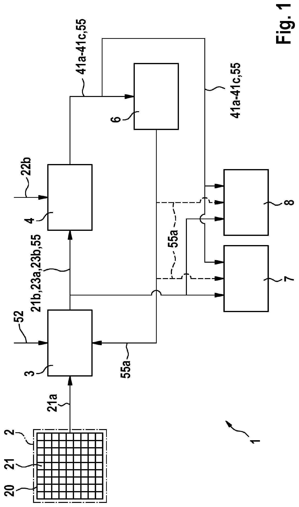
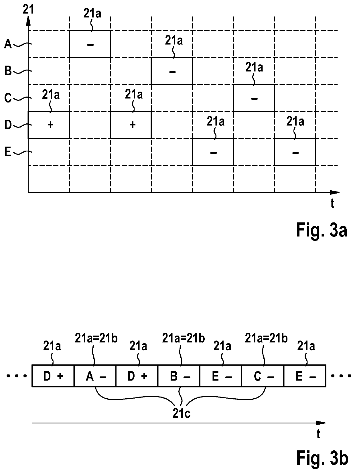
[0041]FIG. 1 shows an exemplary embodiment of the system 1. Physical collection of measurement data is performed by vision sensor 2 that has a light-sensitive area 20, which in turn is divided into individual pixels 21. Whenever the light intensity impinging onto an event-based pixel changes at least by a certain percentage, the vision sensor 2 emits a corresponding event 21a.

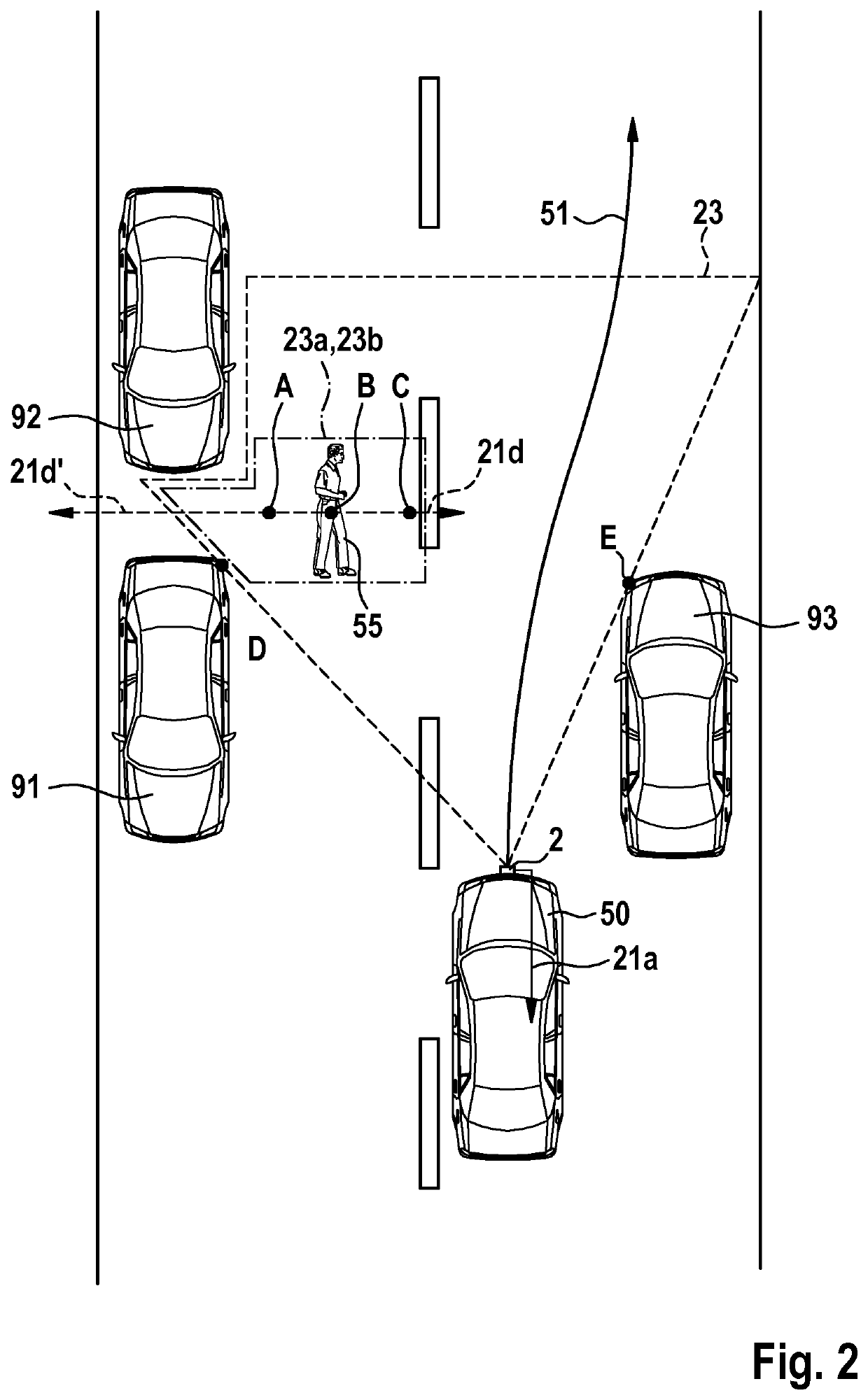
[0042]The discriminator module 3 collects the events 21a from the vision sensor 2, as well as the information 52 about the heading and / or speed of the motion of the primary object 50. This information 52 may be acquired by any appropriate means, e.g., by means of dedicated sensors, or by accessing sensors that are already present somewhere in a vehicle via a bus system to which the sensors are connected (e.g., CAN bus).

[0043]The discriminator module 3 identifies those events 21b that...


PUM


Abstract

A system (1) for detecting dynamic secondary objects (55) that have a potential to intersect the trajectory (51) of a moving primary object (50), comprising a vision sensor (2) with a light-sensitive area (20) that comprises event-based pixels (21), so that a relative change in the light intensity impinging onto an event-based pixel (21) of the vision sensor (2) by at least a predetermined percentage causes the vision sensor (2) to emit an event (21a) associated with this event-based pixel (21), wherein the system (1) further comprises a discriminator module (3) that gets both the stream of events (21a) from the vision sensor (2) and information (52) about the heading and / or speed of the motion of the primary object (50) as inputs, and is configured to identify, from said stream of events (21a), based at least in part on said information (52), events (21b) that are likely to be caused by the motion of a secondary object (55), rather than by the motion of the primary object (50).Vision sensors (2) for use in the system (1).A corresponding computer program.

Description

[0001]The present invention relates to a system for detecting secondary objects that may collide with a moving primary object as early as possible, so that a warning may be issued or collision avoiding action may be taken.BACKGROUND[0002]An analysis of past road accidents has revealed that a large percentage of the accidents occurred because there was simply not enough time left for sufficient collision avoiding action. If there had been just a little more time, in many cases less than a second more, the accident could have been avoided.[0003]To gain this crucial time, automatic emergency brake assistants have been developed. These assistants need a fast and reliable detection of objects with which a moving vehicle might collide. False positives are to be avoided because a needless emergency braking of the vehicle may come as a surprise to following drivers and cause a rear-end collision. But if the processing is more sophisticated, it may take too long.[0004]Some time may be saved ...

Claims


Application Information

Patent Timeline
IPC IPC(8): G06K9/00G06T7/70G06K9/62G06T7/20G08G1/16B60Q9/00B62D15/02B60T7/12B60W30/09B64C39/02G06N3/04G06N3/08
CPCG06K9/00805B60W10/04G06K9/6267G06K9/6217G06T7/20G06K9/00664G08G1/166B60Q9/008B62D15/0265B60T7/12B60W30/09B64C39/024G06N3/04G06N3/08G06T2207/30261G06T2207/30241G06T2207/20084B60W2420/42G06T7/70G06V20/58B60W40/02B60W40/10G06N3/049B60W2554/4029B60W2554/20B60W2420/40G06F18/2413G05D1/0214G05D1/0231G05D1/101B60W2554/40B60W10/18B60W10/20B60W2710/18B60W2710/20G06V20/10G06F18/21G06F18/24B64U2201/10B60W2420/403
Inventor PFEIFFER, MICHAELMARX, JOCHENLANGE, OLIVERPOSCH, CHRISTOPHLAGORCE, XAVIERNIKOLAIDIS, SPIROS
Owner PROPHESEE SA
Why Eureka
Try Eureka