
Method for decorating a mechanical part

a mechanical part and decoration technology, applied in the field of decoration methods of mechanical parts, can solve the problems of very low risk of same becoming detached from this mechanical par

Pending Publication Date: 2021-03-04
COMADUR
View PDF9 Cites 0 Cited by
  • Summary
  • Abstract
  • Description
  • Claims
  • Application Information

AI Technical Summary

Benefits of technology

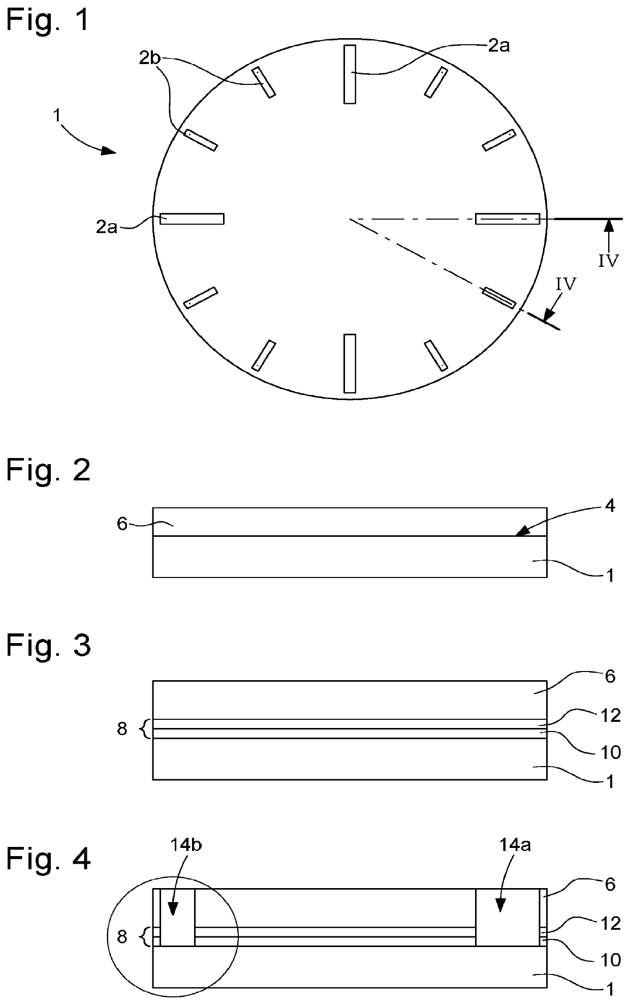
The present invention proposes a method for decorating mechanical parts such as a watch dial or a bezel without causing smears or discarding parts. The method involves directly forming a masking layer on the surface of the mechanical part to be decorated, preventing any risks of the filling material between the mask and the surface. This allows for precise decoration elements with high-quality shape and thickness, and simplifies the process of forming sacrificial masks, finishing decoration elements, and adhesion to the surface of the mechanical part. Additionally, cavities in the surface of the mechanical part further improve adhesion and prevent decoration elements from becoming detached.

Problems solved by technology

More specifically, thanks to the presence of the cavities, the decoration elements are anchored deep within the mechanical part to be decorated and the risks of same becoming detached from this mechanical part are very low.

Method used


Image

  • Method for decorating a mechanical part
  • Method for decorating a mechanical part
  • Method for decorating a mechanical part

Examples


first embodiment

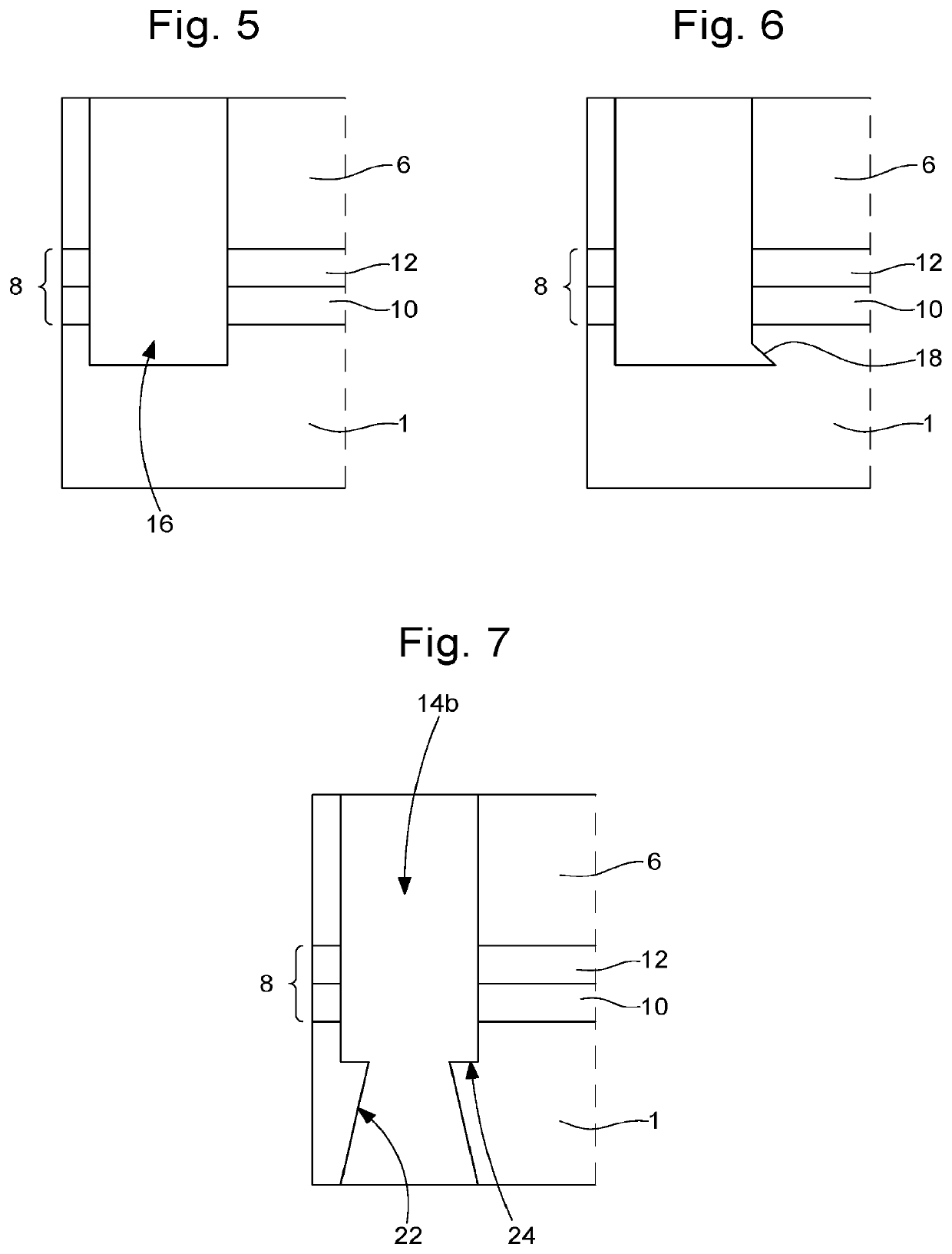
[0060]In order to further improve the immobilisation of the decoration elements 2a, 2b, the cavities 16 are provided with anchoring means. According to the invention (see FIG. 6), these anchoring means are formed by at least one face 18 of the wall 20 of the cavity 16 which, relative to a vertical plane P perpendicular to the surface to be decorated 4 of the watch dial 1, progressively deviates from this vertical plane P as it moves away from said surface to be decorated 4 of the watch dial 1. Thanks to the presence of this inclined face 18, it is understood that once the cavities 16 have been filled with the filling material, the resulting decoration elements 2a, 2b can no longer be dislodged from the cavities 16 and are thus permanently anchored to the watch dial 1.

[0061]Another embodiment of the invention which also aims to improve the anchoring of the decoration elements 2a, 2b on the surface to be decorated 4 of the watch dial 1 provides for boring at least one conical hole 22 ...

second embodiment

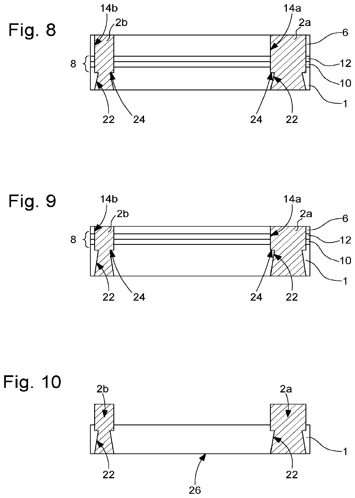
[0067]According to the invention, the openings 14a, 14b made in the masking layer 6 are filled by electro-plating. This technique is used in the event that decoration elements 2a, 2b made of a crystalline metal are sought to be produced. For this purpose, a bath is used in which relevant metal ions and salts are dispersed. The watch dial 1 to be decorated, which is electrically conductive, is connected to an electrode, then immersed in the bath. Using an auxiliary electrode, an electric current is passed through the bath under the effect of which metal ions migrate to the conductive parts of the watch dial 1 in order to form the decoration elements 2a, 2b.

third embodiment

[0068]According to the invention, the decoration elements 2a, 2b are made by injecting a metal. The watch dial 1, covered by the masking layer 6, is placed in an injection machine capable of filling the cavities 16a, 16b with liquid metal in order to create the decoration elements 2a, 2b. In a preferential manner, the metal used is brought to a temperature that is at least greater than the glass transition temperature Tg thereof, and is cooled quickly enough to prevent the atoms thereof from reorganising into a crystalline structure.

[0069]It should be noted that, before filling the volume delimited by the masking layer 6 and the surface to be decorated 4 of the watch dial 1, the masking layer 6 can be levelled to obtain a planar surface parallel to the surface to be decorated 4 of the watch dial 1.

[0070]As already stipulated above, the thickness of the masking layer 6 can be determined to be 400 μm for example. At this stage of the invention, the thickness of the decoration elements...


PUM

PropertyMeasurementUnit
depthaaaaaaaaaa
thicknessaaaaaaaaaa
thicknessaaaaaaaaaa

Abstract

A method for decorating the surface of a mechanical part including structuring, on the surface to be decorated, a masking layer having a thickness that is at least equal to the thickness of the decoration element to be produced; making, in the masking layer, at least one opening that coincides with the location on the surface to be decorated where the decoration element is to be produced, the opening having a contour that is identical to the contour of the decoration element and defining a volume with the mechanical part; filling the volume delimited by the masking layer and the surface to be decorated of with a filling material wherein the decoration elements are sought to be produced; and removing the masking layer.

Description

TECHNICAL FIELD OF THE INVENTION[0001]The present invention relates to a method for decorating a mechanical part. More specifically, the invention relates to a method for decorating a mechanical part used in the horological or jewelry field.BACKGROUND OF THE INVENTION[0002]Numerous methods for producing raised decorations on a surface of a mechanical part such as a watch dial or a bezel are known in the prior art.[0003]A certain number of these known methods consist of manufacturing the decoration elements separately from the mechanical part to be decorated, then of fastening these decoration elements to the mechanical part for which they are intended.[0004]Another method for decorating a mechanical part such as a dial is known from the European patent application EP 2 370 865 A1 filed by The Swatch Group Research and Development Ltd. This decoration method consists of:[0005]taking the mechanical part to be decorated;[0006]making a mask of the plate type, the thickness thereof being...

Claims


Application Information

Patent Timeline
Patent Type & Authority Applications(United States)
IPC IPC(8): B05D1/32G04B19/10B05D5/06G04B37/22
CPCB05D1/322G04B37/22B05D5/06G04B19/10C25D5/12C25D5/022C25D5/48C25D7/005G04B19/18G04D3/0048B22D19/00G04B45/0076A44C17/02A44C17/04B44C1/227B44C1/228B44C1/26
Inventor NETUSCHILL, ALEXANDREBONTAZ, FABIEN
Owner COMADUR
Learn More