
Polyamide Particles and Methods of Production and Uses Thereof

a technology of polyamide particles and polyamide, applied in the direction of coatings, etc., can solve the problems of poor powder flow performance during the 3-d printing process, irregular particulate shapes and wide particle size distributions, and relatively few properties suitable for use in 3-d printing

Pending Publication Date: 2021-03-11
XEROX CORP
View PDF0 Cites 0 Cited by
  • Summary
  • Abstract
  • Description
  • Claims
  • Application Information

AI Technical Summary

Benefits of technology

The present invention is a new invention that can achieve its goals and advantages through various methods. The examples provided are just a few examples of how the invention can be done. The invention can be modified and practiced in different ways, and all the variations are within the scope of the invention. The invention is suitable for use without certain components or steps, and all values mentioned can have some amount of variation. The invention can be understood by understanding the range of values provided. The patent text uses plain, ordinary meaning for the terms used. The invention can have one or more than one element and the article "a" or "an" refers to one or more than one element.

Problems solved by technology

Incomplete interlayer fusion may result in structural weak points, which may be problematic for printing objects having exacting structural and mechanical tolerances.
Although a wide array of thermoplastic polymers are known, there are relatively few having properties suitable for use in 3-D printing, particularly when using powder bed fusion (PBF).
Commercial powder particulates are oftentimes obtained by cryogenic grinding or precipitation processes, which may result in irregular particulate shapes and wide particle size distributions.
Irregular particulate shapes may result in poor powder flow performance during 3-D printing processes.
In addition, powder particulates having shape irregularity, especially those obtained from current commercial processes, may afford poor packing efficiency following deposition and consolidation, thereby resulting in extensive void formation in a printed object due to the powder particulates not packing closely together during deposition.
Wide particle size distributions may be similarly problematic in this regard.
Although poor powder flow performance may be addressed to some degree through dry blending with fillers and flow aids, these techniques may have limited effectiveness with softer polymer materials, such as elastomers, due to particulate aggregation.

Method used


Image

  • Polyamide Particles and Methods of Production and Uses Thereof
  • Polyamide Particles and Methods of Production and Uses Thereof
  • Polyamide Particles and Methods of Production and Uses Thereof

Examples


example 1

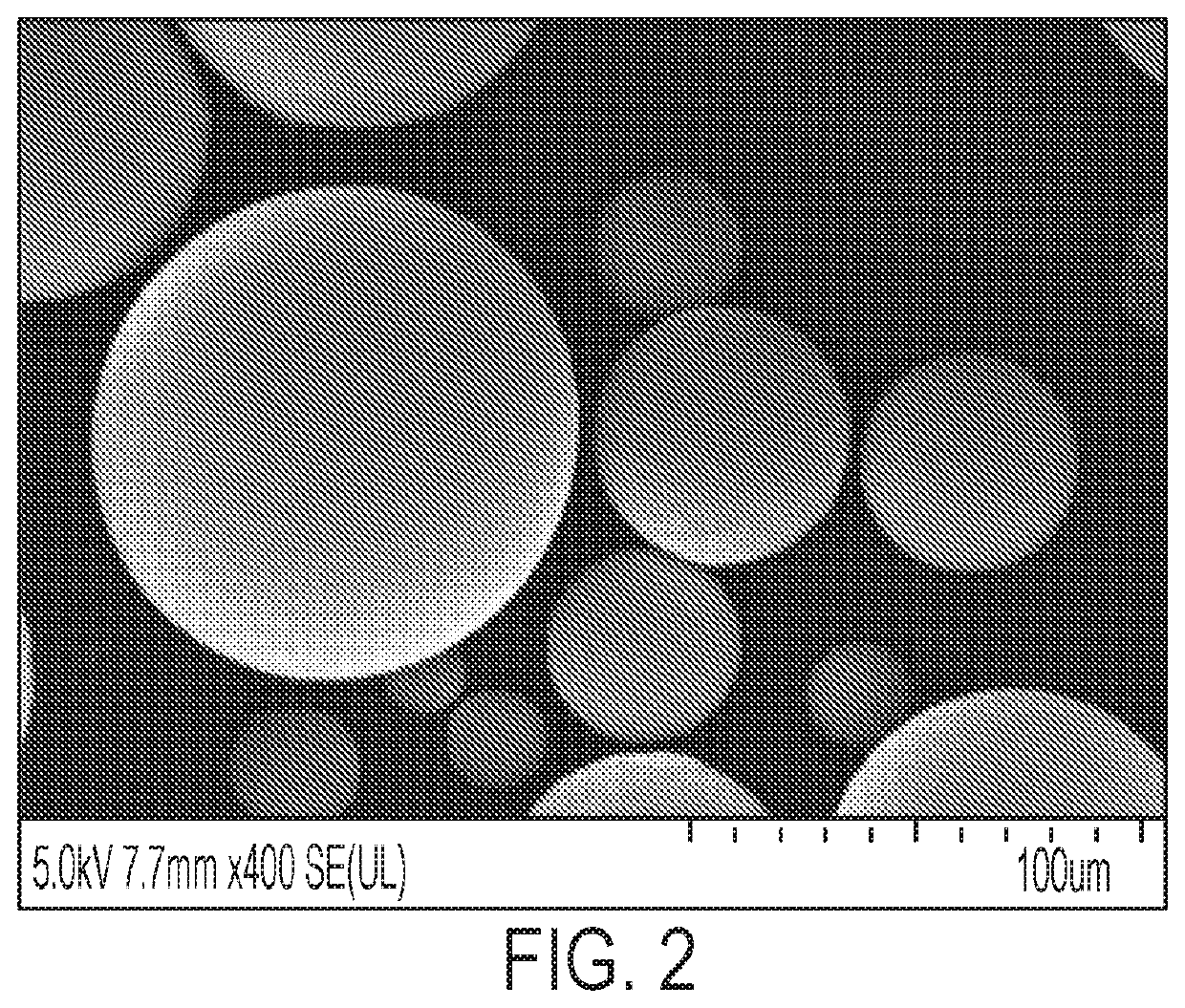
[0195]A 1 L stirred reactor from Parr Instruments was used to prepare polyamide 6 particles by melt emulsification. The reactor was loaded with 20 wt % polyamide 6 and 80 wt % 10,000 cSt PDMS oil. The mixture was then heated to 225° C. while stirring at 1000 rpm using a dual 4-blade propeller. After about 60 minutes, the mixture was discharged from the reactor onto dry ice to quench the mixture. The mixture was then filtered and washed to recover the polymer particles. The resultant polymer particles were passed through a 150-μm sieve. Approximately, 40 wt % of the polyamide 6 loaded into the reactor passed through the 150-μm sieve. FIG. 2 is an SEM micrograph of the particles after sieving, which illustrates the range of particle sizes as large.

example 2

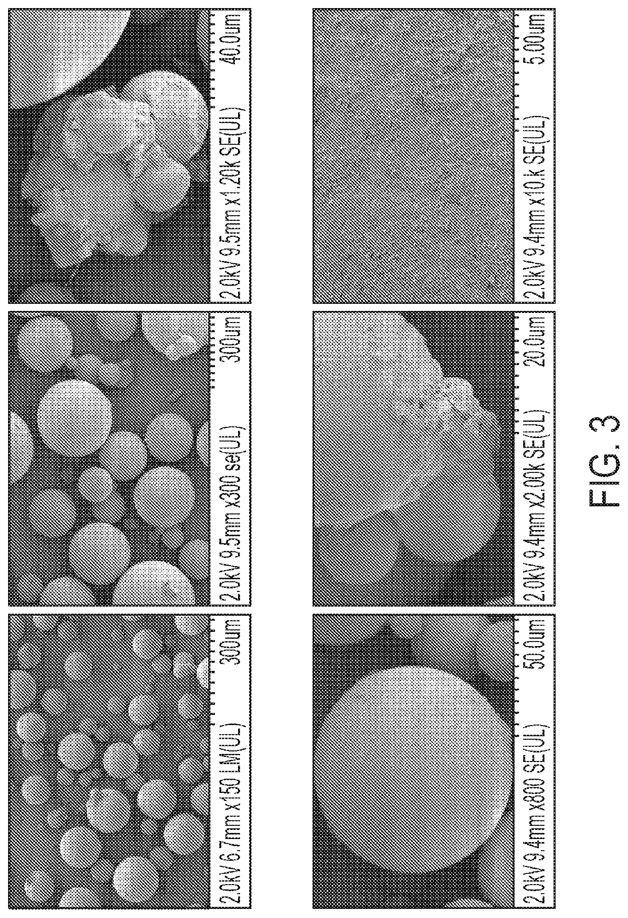
[0196]A 2 L glass reactor from Buchi AG was used to prepare polyamide 12 particles by melt emulsification. The reactor was loaded with 1 wt % AEROSIL® R812S silica nanoparticles (by weight of the polyamide 12 in the final mixture) in 10,000 cSt PDMS oil. The mixture was heated to 200° C. before adding 23 wt % polyamide 12 pellets relative to the combined weight of the PDMS oil and polyamide 12. The reactor was mixed at 500 rpm for 30 minutes. The resultant mixture was discharged and cooled to ambient temperate at a rate of about 1° C. to about 3° C. per minute. The mixture was then washed with heptane and filtered through a 90 mm WHATMAN® #1 paper filter to recover the polymer particles. The resultant polymer particles were air dried overnight in a fume hood. The dried particles have a D50 of about 227 μm, and the dried particles passed through a 150-μm sieve have a D50 of about 124 μm.

example 3

[0197]Polyamide 12 particles (Samples 3-1 to 3-44) were prepared by melt emulsification in a 1 L glass kettle reactor. 10,000 cSt PDMS oil, 23% polyamide 12 (from RTP, EMX-Grivory, or from Arkema) relative to the combined weight of the PDMS oil and polyamide 12, and a desired amount of silica nanoparticles (AEROSIL® R812S or AEROSIL® RX50) by weight of polyamide 12 were added to the glass kettle. The order of addition was either (c) PDMS oil and silica nanoparticles mixed to a good dispersion then polyamide added or (d) PDMS oil, polyamide, and silica nanoparticles added before mixing. The nitrogen headspace purge was then turned on, and the mixture heated to a desired temperature (e.g., 200° C., 210° C., or 220° C.) over 90 minutes at 260 rpm. Once at temperature, the rotor speed was increased to a desired rpm. Samples were taken at various times. Once complete, heating and stirring were turned off, and the reactor was allowed to cool to room temperature before discharging the mixt...


PUM

PropertyMeasurementUnit
wt %aaaaaaaaaa
melting pointaaaaaaaaaa

Abstract

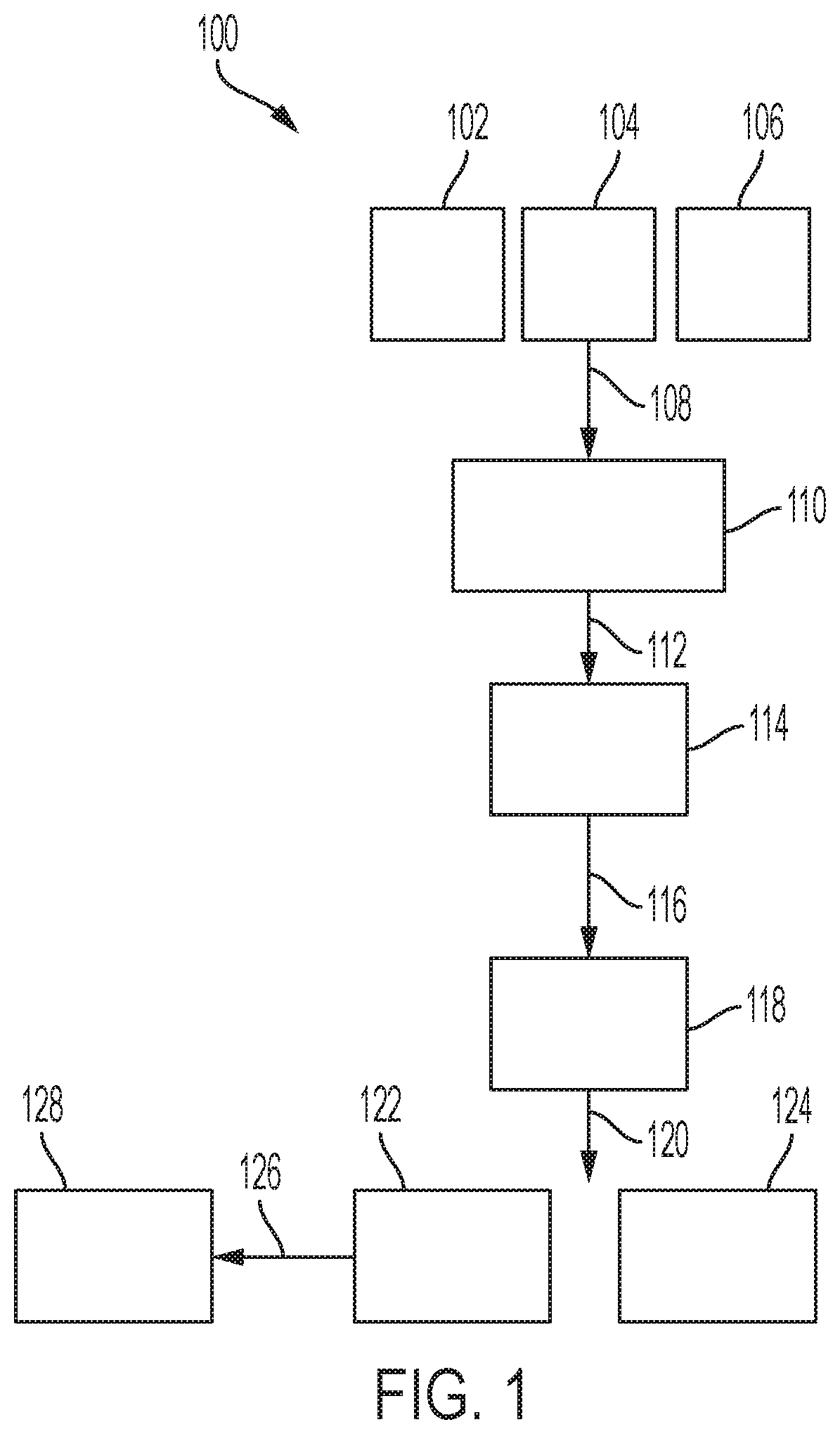
A method for producing polyamide particles may include: mixing a mixture comprising a polyamide, a carrier fluid that is immiscible with the polyamide, and nanoparticles at a temperature greater than a melting point or softening temperature of the polyamide and at a shear rate sufficiently high to disperse the polyamide in the carrier fluid; cooling the mixture to below the melting point or softening temperature of the polyamide to form solidified particles comprising polyamide particles having a circularity of 0.90 or greater and that comprise the polyamide and the nanoparticles associated with an outer surface of the polyamide particles; and separating the solidified particles from the carrier fluid.

Description

TECHNICAL FIELD[0001]The present disclosure relates to polyamide particles and methods of making such particles. Such particles, especially the highly spherical polyamide particles, may be useful, among other things, as starting material for additive manufacturing.BACKGROUND[0002]Three-dimensional (3-D) printing, also known as additive manufacturing, is a rapidly growing technology area. Although 3-D printing has traditionally been used for rapid prototyping activities, this technique is being increasingly employed for producing commercial and industrial objects, which may have entirely different structural and mechanical tolerances than do rapid prototypes.[0003]3-D printing operates by depositing either (a) small droplets or streams of a melted or solidifiable material or (b) powder particulates in precise deposition locations for subsequent consolidation into a larger object, which may have any number of complex shapes. Such deposition and consolidation processes typically occur ...

Claims


Application Information

Patent Timeline
Patent Type & Authority Applications(United States)
IPC IPC(8): C08G69/46C08L77/00C08J3/215B29B9/16
CPCC08G69/46C08L77/00C08J2377/00B29B9/16B29B2009/163C08J3/215C08J3/16C08K3/36C08K2201/011C08J2377/02C08L77/02C08L77/06C08K3/04C08J3/12C08J2377/06C08J3/226C08K3/22
Inventor FARRUGIA, VALERIE M.WANG, YULINHUANG, CHU YINMOORLAG, CAROLYN PATRICIA
Owner XEROX CORP
Learn More