
Battery system, battery module and battery control circuit thereof

Active Publication Date: 2021-03-11
RICHTEK TECH
View PDF0 Cites 3 Cited by
  • Summary
  • Abstract
  • Description
  • Claims
  • Application Information

AI Technical Summary

Benefits of technology

The present invention provides a battery system with multiple battery modules that can communicate with each other using a communication interface protocol. The battery modules can operate in different modes and can be designated as the first or second module based on their position in the chain. The battery control circuit in the first module includes a battery unit and a battery control circuit that can detect the battery unit's voltage and control it. The battery control circuit generates a data signal with a predetermined number of clock pulses that compensates for clock differences caused by the communication interface protocol. The battery control circuit can also receive data input and output signals and confirm the target module has received the data. The battery system can turn off the current connection path when a fault occurs. The technical effects of this invention include improved synchronization and communication between battery modules in a battery system.

Problems solved by technology

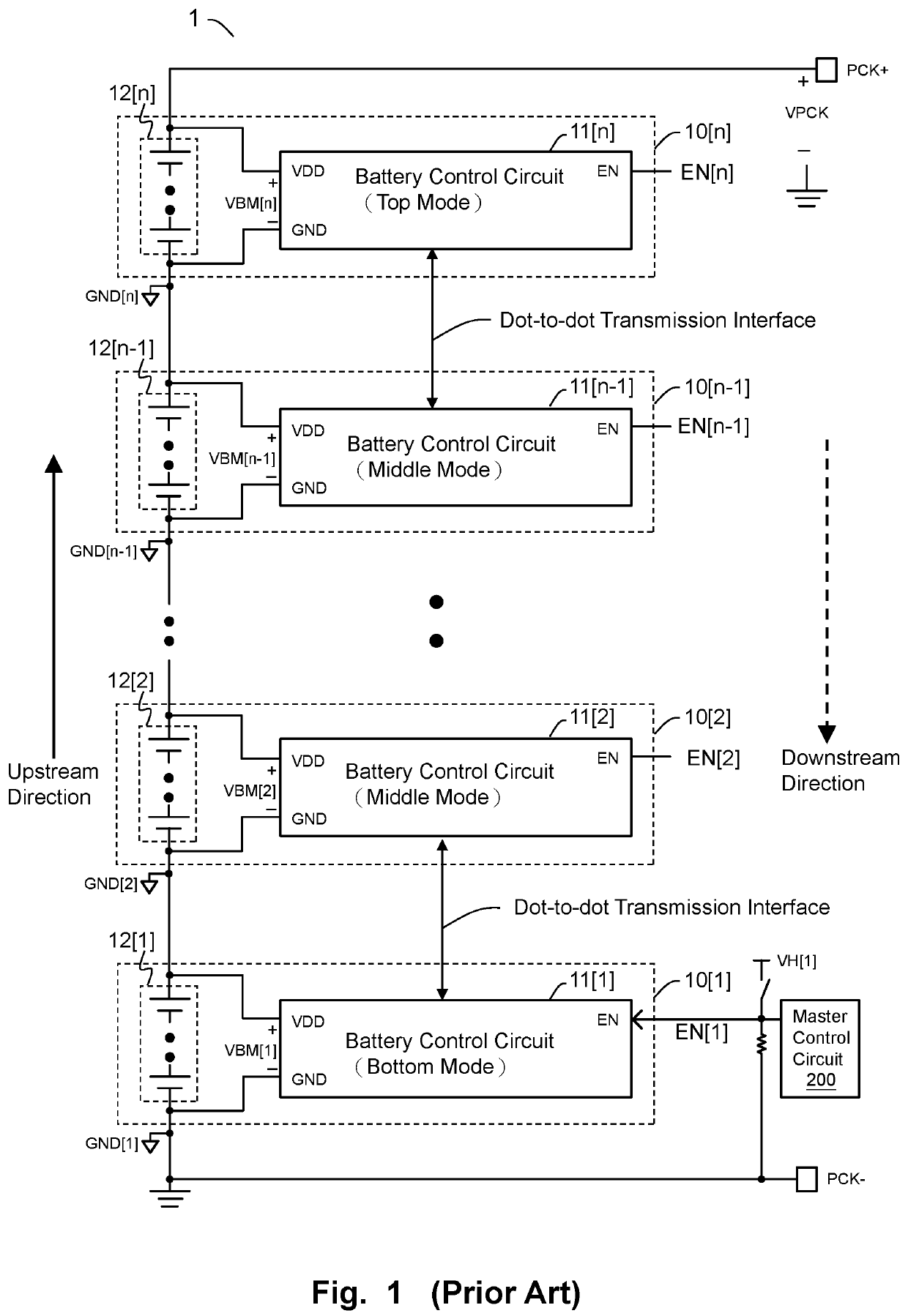
The prior art in FIG. 1 has a drawback that: because the battery modules are connected to one another by daisy chain configuration, data communication among respective battery modules are performed via dot-to-dot transmission.
This leads to complicated design for the battery modules and more power consumption.

Method used


Image

  • Battery system, battery module and battery control circuit thereof
  • Battery system, battery module and battery control circuit thereof
  • Battery system, battery module and battery control circuit thereof

Examples


Embodiment Construction

[0027]The drawings as referred to throughout the description of the present invention are for illustration only, to show the interrelations between the circuits and the signal waveforms, but not drawn according to actual scale of circuit sizes and signal amplitudes and frequencies.

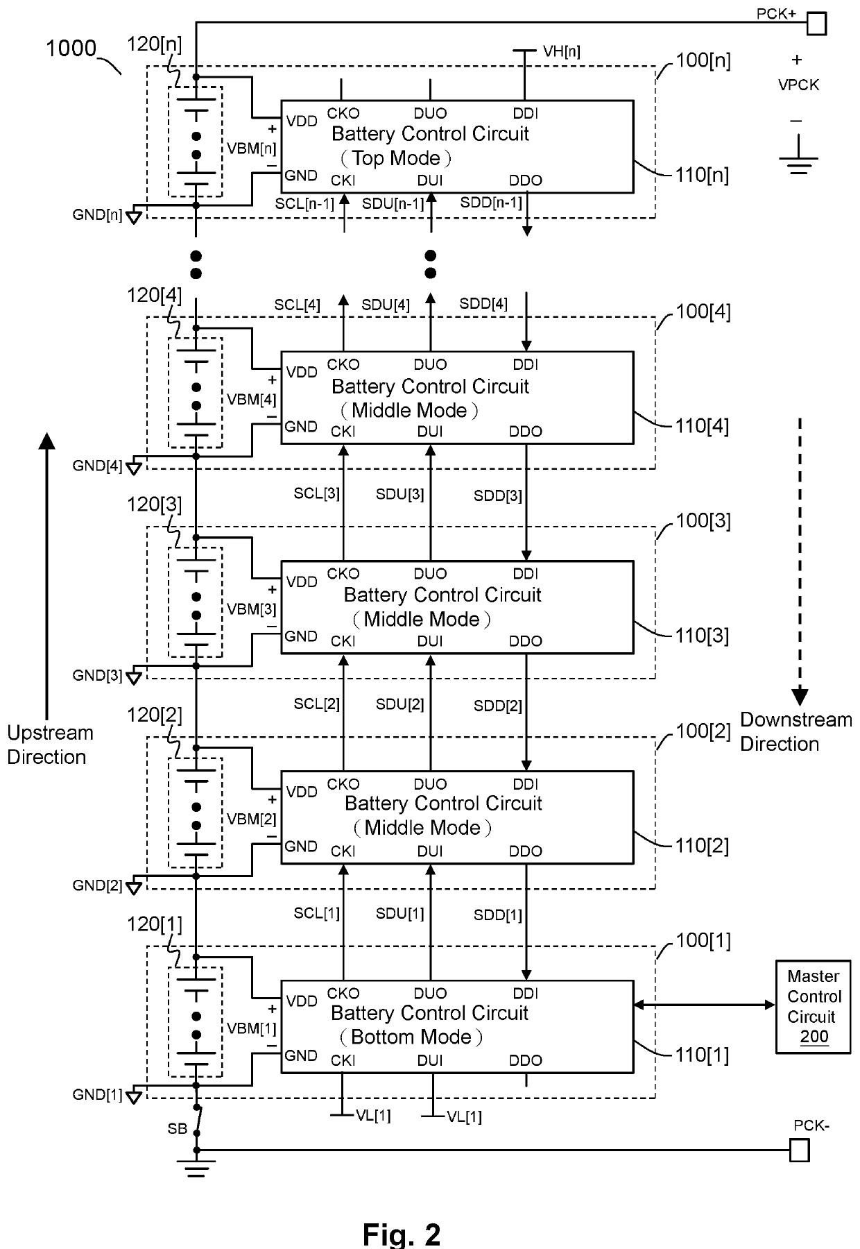
[0028]Please refer to FIG. 2, which shows a schematic diagram of a battery system (i.e., battery system 1000) according to an embodiment of the present invention. As shown in FIG. 2, in one embodiment, the battery system 1000 includes battery modules 100[1]˜100[n]. The battery modules 100[1]˜100[n] are connected to one another in daisy-chain configuration and communicate with one another through the daisy chain according to a communication interface protocol. The communication interface protocol performs data communication by data packets wherein each data packet has a predetermined number of clock pulses for performing synchronous data communication. The battery modules 100[1]˜100[n] are arranged in such ...


PUM


Abstract

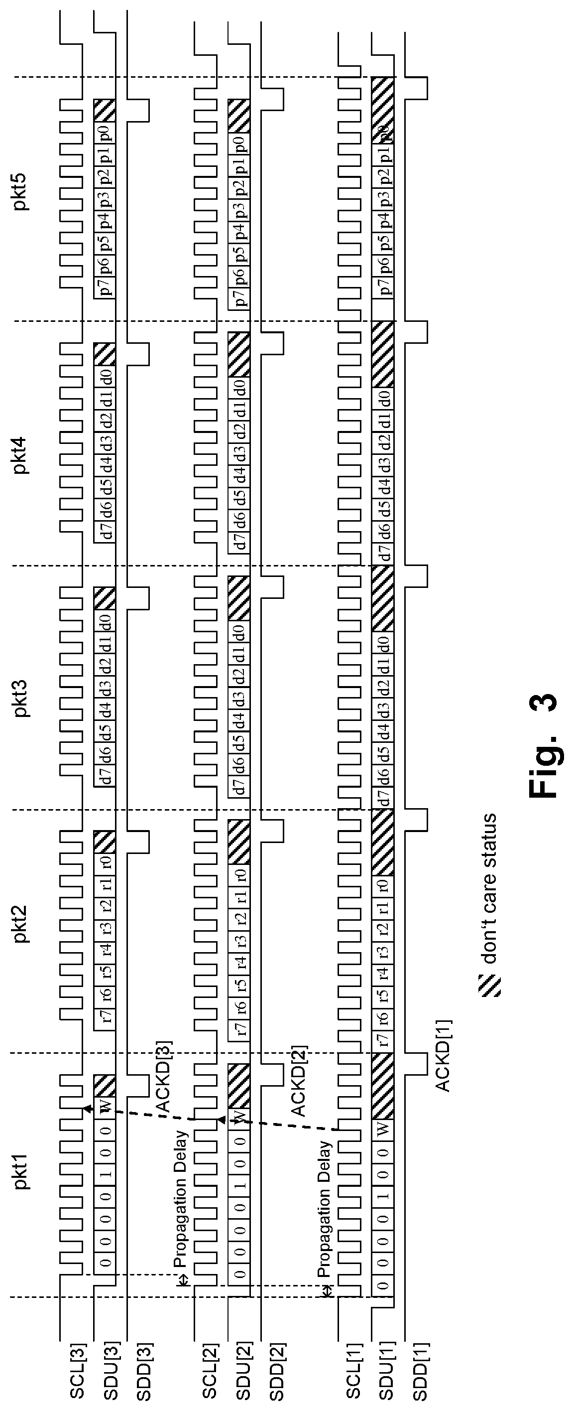
A battery module for use in a battery system is coupled with other battery modules in the battery system in daisy-chain configuration. And, the battery module communicates with other battery modules through the daisy chain according to a communication interface protocol which has a predetermined number of clock pulses. The battery module includes a battery unit and a battery control circuit. When the battery module operates in a bottom mode, the battery control circuit generates an upstream clock output signal which includes the predetermined number of clock pulses plus a number of inserted clock pulses, to compensate a clock difference caused by the propagation delay of the daisy chain, such that the battery module is able to synchronously receive a downstream data signal transmitted from the target module via the daisy chain as the battery module is transmitting an upstream clock output signal.

Description

CROSS REFERENCE[0001]The present invention claims priority to TW 108132658, filed on Sep. 10, 2019.BACKGROUND OF THE INVENTIONField of Invention[0002]The present invention relates to a battery system; particularly, it relates to such battery system having a daisy chain. The present invention also relates to battery modules and battery control circuits for use in such battery system.Description of Related Art[0003]The relevant prior art of which the inventor is aware includes the specification of LTC6804 Multi-cell Monitors, and the following U.S. patents or U.S. patent publications: U.S. Pat. No. 8,010,724 “I2C / SMBUS Ladders and Laddered Enabled ICs”; U.S. patent publication No. 2011 / 0289239 A1 “Device Address Assignment in a Bus Cascade System”; and U.S. patent publication No. 2019 / 0006723 A1 “Multi-Channel and Bi-directional Battery management System”.[0004]A high-power battery system (such as for use in an electric vehicle) includes a large number of battery modules. In the batte...

Claims


Application Information

Patent Timeline
IPC IPC(8): H02J7/00H01M10/42H01M10/48
CPCH02J7/0014H02J7/00032H02J7/0047H01M2010/4271H01M10/482H02J7/00308H01M2010/4278H01M10/425H02J7/0016H02J7/00036Y02T10/70Y02E60/10H01M10/4207H01M10/44H01M10/48
Inventor CHANG, WEI-HSU
Owner RICHTEK TECH
Learn More