Supercharge Your Innovation With Domain-Expert AI Agents!

Motor controller and motor control method

Active Publication Date: 2021-03-11
MIDASTEK MICROELECTRONICS
View PDF0 Cites 1 Cited by
  • Summary
  • Abstract
  • Description
  • Claims
  • Application Information

AI Technical Summary

Benefits of technology

The motor controller and method described in this patent allows for the direct calculation of the real rotor angle of a three-phase alternating current motor without using a rotor angle sensor. This is achieved by using the three phase current values of the motor. By adjusting the voltage control signals based on the expected rotor speed and the calculated real rotor angle, the motor's real rotor speed can be controlled effectively. This not only reduces the hardware costs associated with the rotor angle sensor, but also improves the efficiency of the three-phase alternating current motor.

Problems solved by technology

However, in the foregoing conventional method, entire costs of the three-phase alternating current motor (or a motor control configured to control the three-phase alternating current motor) are increased because a rotor angle sensor (such as an encoder, a rotating transformer, or a Hall sensor) is required to be disposed.
However, in the foregoing methods, a complex arithmetic unit is required to be disposed, and the arithmetic unit is required to be designed for specification parameters related to the three-phase alternating current motor and the algorithms.
In other words, in the current known estimation algorithms, costs still cannot be effectively reduced, and an application range is narrowed as a result of an additional customized design required for a respective three-phase alternating current motor.

Method used


Image

  • Motor controller and motor control method
  • Motor controller and motor control method
  • Motor controller and motor control method

Examples


embodiment 1

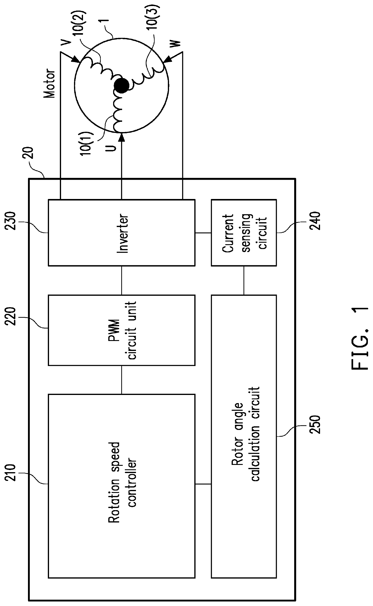
[0022]FIG. 1 is a schematic block diagram of a motor controller according to Embodiment 1 of the invention. Referring to FIG. 1, in the present embodiment, a motor controller 20 is electrically connected to a motor 1 and is configured to control the motor 1. The motor controller 20 includes a rotation speed controller 210, a pulse width modulation (PWM) circuit unit 220, an inverter (also referred to as a converter) 230, a current sensing circuit 240, and a rotor angle calculation circuit 250. The motor 1 includes stator windings 10(1)-10(3), the stator windings 10(1)-10(3) receiving three phase currents U, V, and W outputted by the motor controller 20 to change a magnetic field vector of the motor 1, so that a rotor of the motor 1 rotates. It should be noted that, in the present embodiment, the motor 1 is a three-phase alternating current motor, and neither of the motor 1 and the motor controller 210 has a rotor angle sensor / rotor address sensor that is configured to directly sense...

embodiment 2

[0054]A difference between Embodiment 2 and Embodiment 1 lies in an implementation of the rotor angle calculation circuit 250. Other hardware elements are the same as those of Embodiment 1, and therefore the descriptions thereof are omitted herein.

[0055]In particular, the rotor angle calculation algorithm implemented on the rotor angle calculation circuit 250 in Embodiment 2 defines relationships between three phase current values Iu, Iv, and Iw and the real rotor angle θe through the following formulas (2-1), (2-2), and (2-3):

Iu=sinθe,(2-1)Iv=sin(θe+120)=sinθecos120+cosθesin120=-12sinθe+32cosθe,and(2-2)Iw=sin(θe+240)=sinθecos240+cosθesin240=-12sinθe-32cosθe.(2-3)

[0056]θe is the real rotor angle with a unit of degree; Iu is the U-phase current value, Iv is the V-phase current value, and Iw is the W-phase current value with a unit of ampere (A).

[0057]Similarly, with the relationships defined above, a formula for calculating the real rotor angle θe may be derived using two of the thre...

embodiment 3

[0064]A difference between Embodiment 3 and Embodiment 1 lies in an implementation of the rotor angle calculation circuit 250. Other hardware elements are the same as those of Embodiment 1, and therefore the descriptions thereof are omitted herein.

[0065]In particular, the rotor angle calculation algorithm implemented on the rotor angle calculation circuit 250 in Embodiment 3 defines relationships between the three phase current values Iu, Iv, and Iw and the real rotor angle Be through the following formulas (3-1), (3-2), (3-3):

Iu=cosθe,(3-1)Iv=cos(θe-120)=cosθecos120+sinθesin120=-12cosθe+32sinθe,and(3-2)Iw=cos(θe-240)=cosθecos240+sinθesin240=-12cosθe-32sinθe.(3-3)

[0066]θe is the real rotor angle with a unit of degree; Iu is the U-phase current value, Iv is the V-phase current value, and Iw is the W-phase current value with a unit of ampere (A).

[0067]Similarly, with the relationships defined above, a formula for calculating the real rotor angle θe may be derived using two of the thre...


PUM


Abstract

A motor control method is provided. The method includes: receiving a plurality of voltage control signals from a rotation speed controller to output a plurality of PWM signals; receiving the plurality of PWM signals to output three phase currents, so that a motor rotates; sensing three phase current values of the three phase currents; directly calculating a real rotor angle of the motor according to two of the three phase current values; and adjusting the plurality of the outputted voltage control signals according to an expected rotor speed and the calculated real rotor angle, so as to make the real rotor speed of the motor reach the expected rotor speed.

Description

CROSS-REFERENCE TO RELATED APPLICATION[0001]This application claims the priority benefit of Taiwan application serial no. 108132052, filed on Sep. 5, 2019. The entirety of the above-mentioned patent application is hereby incorporated by reference herein and made a part of this specification.BACKGROUND OF THE INVENTION1. Field of the Invention[0002]The invention relates to a control method, and in particular, to a motor controller of a three-phase alternating current motor that is adapted for a non-address sensor and a motor control method used for the motor controller.2. Description of Related Art[0003]In a conventional three-phase alternating current control method, if a current rotor angle (a rotor address / position) of a motor is required to adjust a rotor speed of the three-phase alternating current motor, a rotor address sensor (also referred to as a rotor angle sensor or an address sensor) is mostly used to directly sense the rotor angle of the three-phase alternating current m...

Claims


Application Information

Patent Timeline
IPC IPC(8): H02P21/09H02P27/12H02P21/18H02P21/22
CPCH02P21/09H02P21/22H02P21/18H02P27/12H02P23/14H02P21/24H02P27/06
Inventor TSAI, MING-HUNGTAN, CHUNG-PINGCHEN, WEI-TIEN
Owner MIDASTEK MICROELECTRONICS
Features
  • R&D
  • Intellectual Property
  • Life Sciences
  • Materials
  • Tech Scout
  • Unparalleled Data Quality
  • Higher Quality Content
  • 60% Fewer Hallucinations
Learn More