
Balloon basket catheter device

a catheter device and balloon basket technology, applied in the field of balloon basket catheter devices, can solve the problems of impaired dispensing of medication-tpa, poor adaptability to the tortuous vasculature of the venous anatomy, and large blood clots often lodged deep in the greater curvature of the artery, so as to facilitate suction vaccum, prevent backflow, and reduce the chance

Pending Publication Date: 2021-03-25
THROMBOLEX INC
View PDF1 Cites 4 Cited by
  • Summary
  • Abstract
  • Description
  • Claims
  • Application Information

AI Technical Summary

Benefits of technology

The present invention is a system for removing blood clots from arteries that includes a balloon catheter and an infusion basket catheter. The balloon catheter can be inflated to occlude the blood flow and prevent emboli from being carried away during the use of the infusion basket catheter. The balloon has a funnel shape to provide a space for collecting the thrombus and can be adjusted to conform to the anatomy. It also has a suction port for aspirating the thrombus. The system includes an inner lumen within the balloon that allows for the placement of additional guidewires to facilitate the removal of blood clots. The balloon is bordered by contrast agents to allow for better monitoring during the procedure.

Problems solved by technology

Additionally, because the culprit-clot has either partially occluded or fully occluded the blood flow through the vessel, dispersion of the medication-tPA may be impaired.
CDT devices may additionally employ expandable baskets to mechanically open within a blood clot that resides inside of a vessel, but these expandable baskets typically function best in straight vessels and are not well adapted to the tortuous vasculature of the venous anatomy.
For example, in the case of a pulmonary embolism and the anatomy of the pulmonary artery, large blood clots are often lodged deep in the greater curvature of the artery and are difficult to treat.
Concurrent monitoring of important vital signs within the occluded vessel, such as blood pressures and oxygen stats, is also not possible during deployment of current single lumen CDT devices.

Method used


Image

  • Balloon basket catheter device
  • Balloon basket catheter device
  • Balloon basket catheter device

Examples


Embodiment Construction

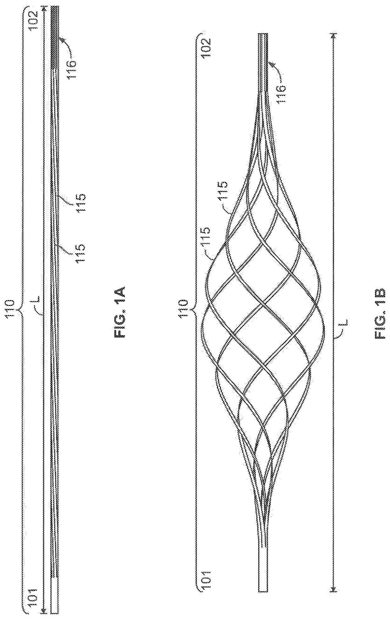
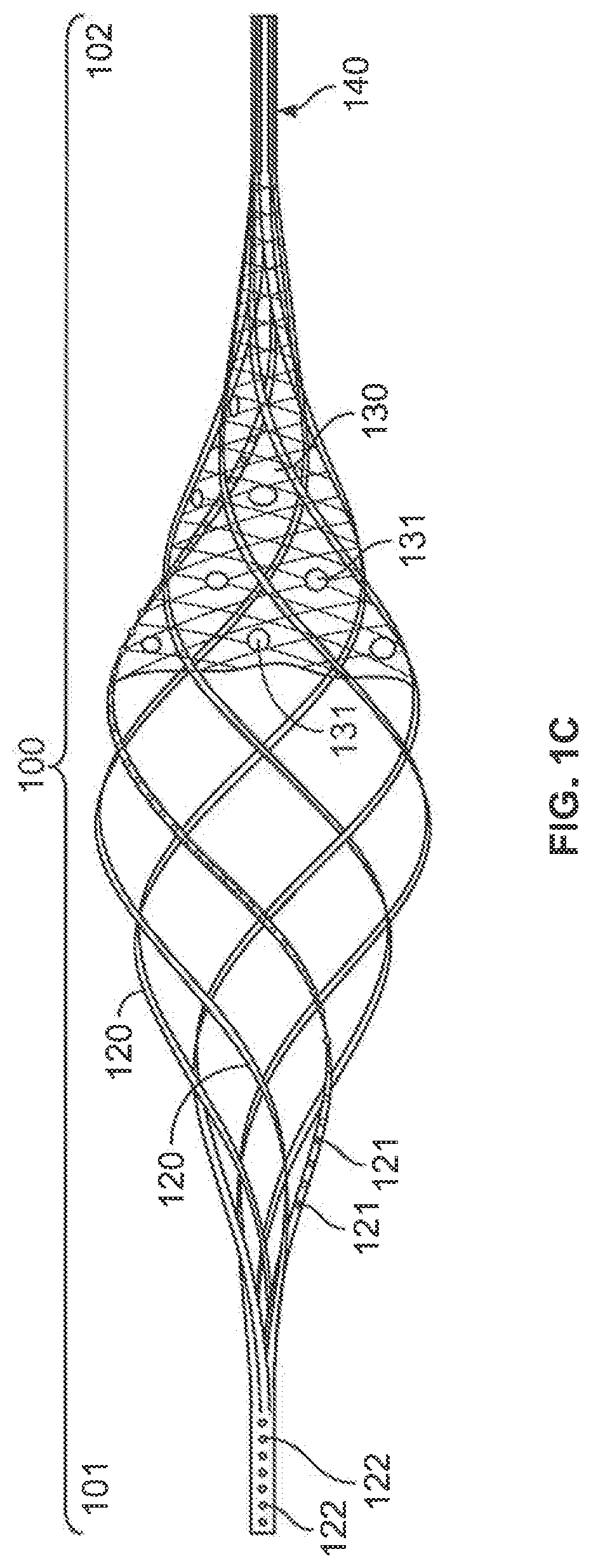
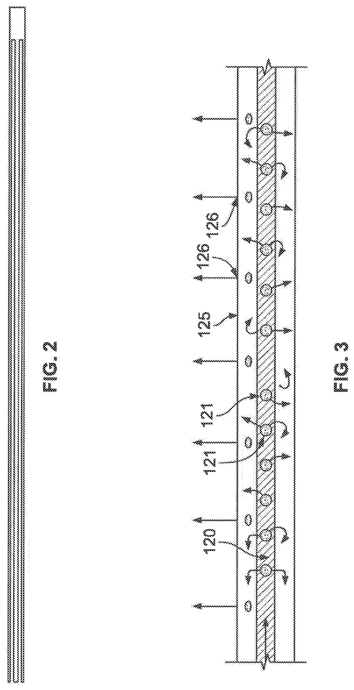
[0045]The present invention will now be described more fully hereinafter. However, many modifications and other embodiments of the present invention set forth herein will come to mind to one skilled in the art to which the invention pertains having the benefit of the teachings presented in the foregoing descriptions. Therefore, it is to be understood that the present invention is not to be limited to the specific embodiments disclosed and that modifications and other embodiments are intended to be included within the scope of the appended claims.

[0046]Reference throughout this specification to features, advantages, or similar language does not imply that all of the features and advantages that may be realized with the present disclosure should be or are in any single embodiment of the disclosure. Rather, language referring to the features and advantages is understood to mean that a specific feature, advantage, or characteristic described in connection with an embodiment is included ...


PUM

PropertyMeasurementUnit
Lengthaaaaaaaaaa
Luminous fluxaaaaaaaaaa

Abstract

The present disclosure relates to catheter system comprising a balloon and an infusion basket designed to be deployed in complex vasculature to optimally treat vascular and arterial disease conditions such as blood clots, blood emboli, and deep vein thrombosis. The basket may comprise a shaft with a plurality of cuts along a portion of its length to form a plurality of tines that provide support for a plurality of porous tubes to form the limbs of the basket. The limbs of the basket expand radially away from the longitudinal axis of the basket when the longitudinal length of the basket is reduced. The limbs may also be connected to a drug delivery system, and in this manner, baskets of the present disclosure allow for the use of both mechanical and pharmaceutical means of thrombolysis and thrombectomy.

Description

CROSS-REFERENCE TO RELATED APPLICATION[0001]This patent document claims priority to U.S. Provisional Patent Application No. 62 / 905,632, filed Sep. 25, 2019. The disclosure of the priority application is fully incorporated by reference.FIELD OF THE INVENTION[0002]The present invention relates to a mechanically deployable balloon basket catheter device and methods of treatment of arterial and venous thromboembolic disorders, including, pulmonary embolism and deep vein thrombosis.BACKGROUND OF THE INVENTION[0003]Conventional methods for catheter-directed thrombolysis (CDT) involves infusion of clot dissolving medication, such as recombinant tissue plasminogen (r-tPA) via a single lumen infusion catheter, which is typically much smaller in diameter than the vessel in which the single lumen infusion catheter is placed. Additionally, because the culprit-clot has either partially occluded or fully occluded the blood flow through the vessel, dispersion of the medication-tPA may be impaired....

Claims


Application Information

Patent Timeline
IPC IPC(8): A61M25/10A61M25/00
CPCA61M25/104A61M25/0026A61M2205/0266A61M2025/1086A61M2205/0216A61M2025/105A61F2/013A61M2025/1052A61M2025/1065A61M25/10A61M25/0082A61M2025/1093A61M2025/0046A61M2025/0047A61M2025/0024A61F2/0108A61F2002/016A61B2017/22084A61B17/221A61B2017/22079A61B17/22A61B2217/005A61B2017/22067A61B2017/22051
Inventor GREEN, NICHOLASEVANS, SAMUEL
Owner THROMBOLEX INC
Learn More