
Pipe member, gasification combined power generation device, and pipe member assembly method

Pending Publication Date: 2021-03-25
MITSUBISHI HEAVY IND LTD
View PDF0 Cites 0 Cited by
  • Summary
  • Abstract
  • Description
  • Claims
  • Application Information

AI Technical Summary

Benefits of technology

The invention is about a way to make sure that pipes with a liner are resistant to both wear and corrosion, while also minimizing the difference in how much they expand or contract with changes in temperature.

Problems solved by technology

Although there is also a method of performing build-up welding of a nickel-containing alloy material such as stainless steel on a portion of the raw syngas pipe, in which a wall thickness decrease or corrosion is observed, to ensure corrosion resistance, cracks are generated in the welded portion in some cases, increasing costs.

Method used


Image

  • Pipe member, gasification combined power generation device, and pipe member assembly method
  • Pipe member, gasification combined power generation device, and pipe member assembly method
  • Pipe member, gasification combined power generation device, and pipe member assembly method

Examples


first modification example of embodiment

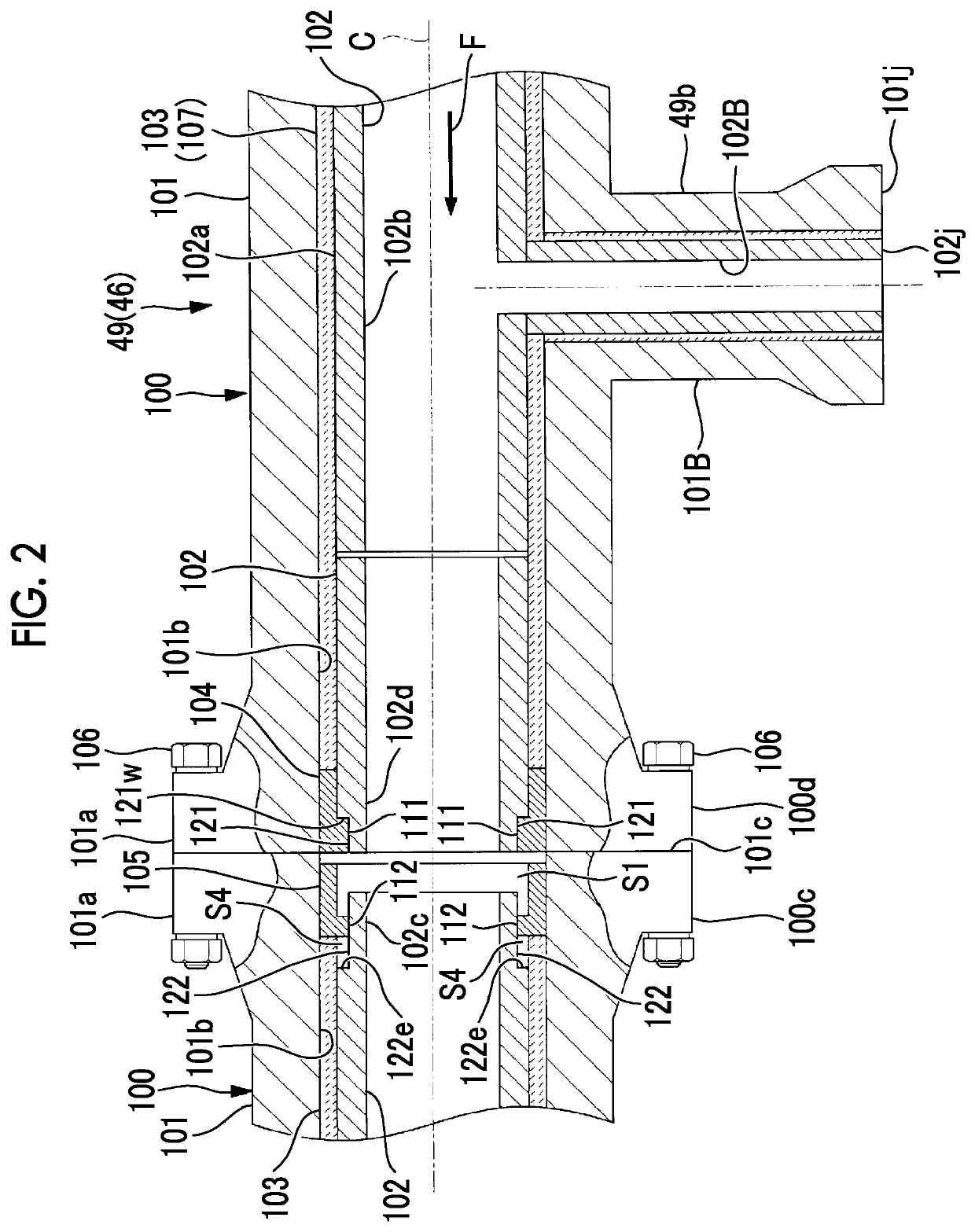
[0087]As illustrated in FIG. 4, in a case of disposing the plurality of liners 102 in series in the outer pipe 101, the first liner holding member 104 may be provided not only at the end portion 100d of the pipe member 100 on the downstream side in the flowing direction F but also on the outer peripheral side of the end portion 102d of at least one of the other liners 102 on the downstream side in the flowing direction F. In addition, other configurations and relationships thereof are the same as in the embodiment illustrated in FIGS. 2 and 3.

[0088]In this case, a gap S3 is provided in the pipe axis C direction between the first liner holding member 104 and the other liner 102 positioned on the downstream side in the flowing direction F from the first liner holding member 104. Accordingly, a thermal elongation difference between the other liner 102 on the downstream side and the outer pipe 101 is allowed, and thereby an effect thereof can be suppressed.

[0089]In addition, the number ...

second modification example of embodiment

[0090]In addition, as illustrated in FIG. 5, in at least a part of the gas generation line 49 and the char return line 46, a pipe member 100R used in an elbow portion 49E at which the pipe axis C direction curves may be used. The pipe member 100R includes an outer pipe 1018 that has a curved portion 101w, which is formed to curve with a predetermined curvature radius, and a plurality of liners 102R which are inserted and disposed in series along the pipe axis C direction inside the outer pipe 101. In addition, the pipe member 100R may include the fireproof material 103 filling between the outer pipe 1018 and a liner 12R. In addition, other configurations and relationships thereof are the same as in the embodiment illustrated in FIGS. 2 and 3.

[0091]The plurality of liners 102R each are formed to curve with the same curvature radius as the curved portion 101w of the outer pipe 101R, and are divided to have a length that allows easy insertion and disposition in the outer pipe 101R. In ...


PUM

PropertyMeasurementUnit
Radiusaaaaaaaaaa

Abstract

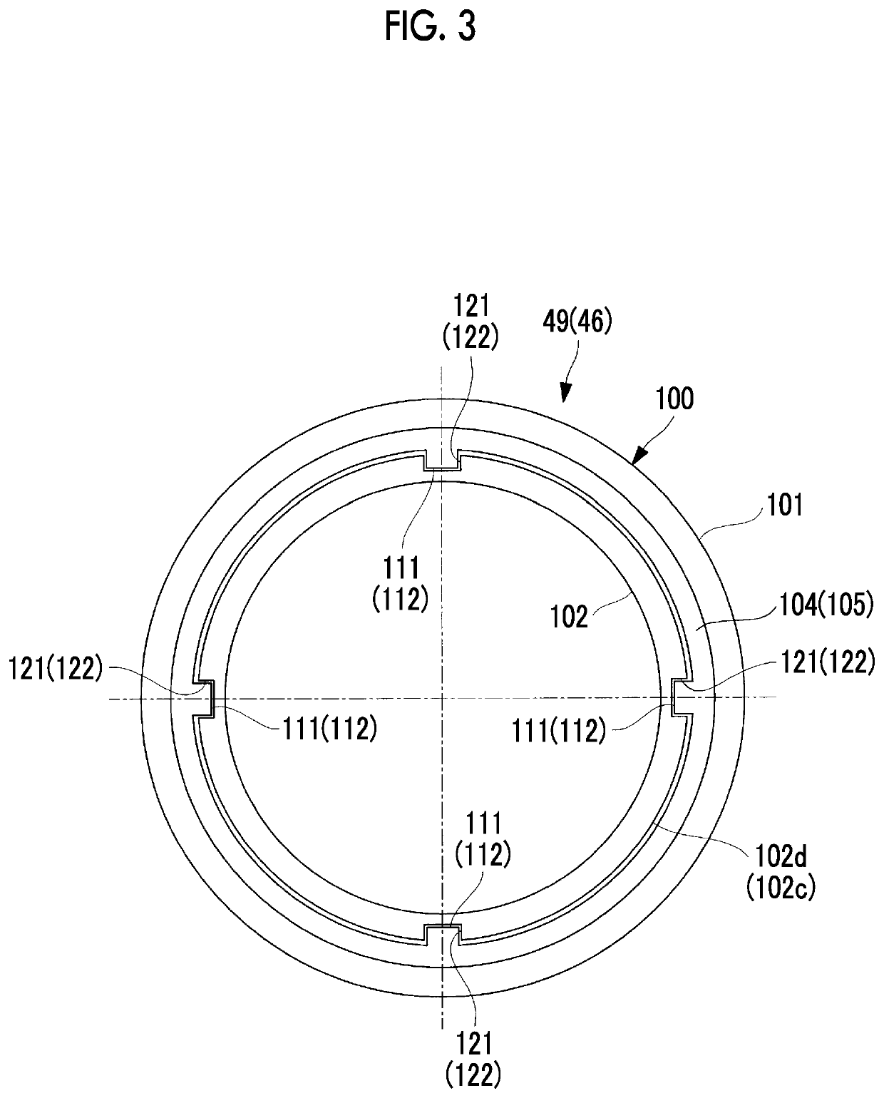
In order to allow for thermal elongation of a liner, a pipe member, in the interior of which flows a fluid containing solids, is provided with: a tubular outer pipe; a single tubular liner provided inside the outer pipe with a gap therebetween in the radial direction, or a plurality thereof arranged serially in the direction of the pipe axis C; a refractory material filled in between the outer pipe and the liner; a first liner holding member that is provided on an end portion side of the outer pipe, and that holds the liner arranged on the end portion side in a restrained state in the pipe axis C direction and the circumferential direction around the pipe axis C; and a second liner holding member that is provided on an end portion side of the outer pipe, and that holds the liner arranged on the end portion side.

Description

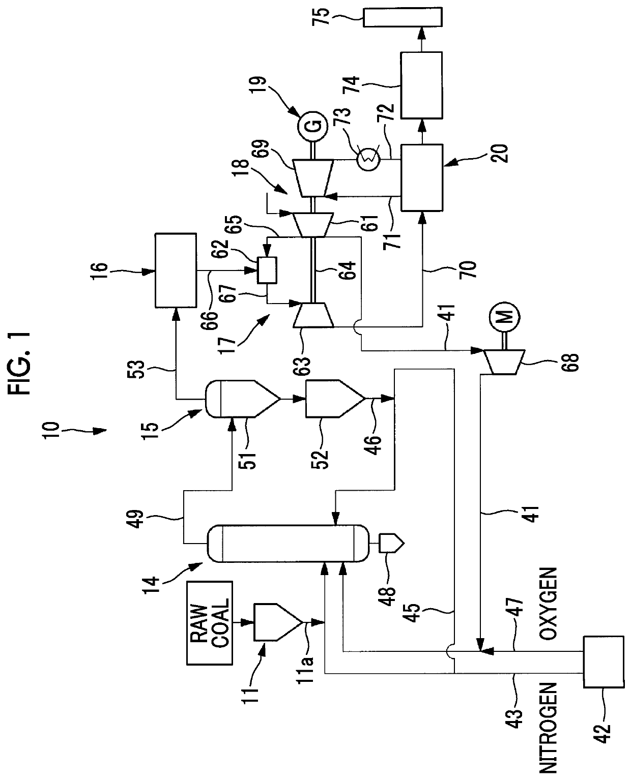
TECHNICAL FIELD[0001]The present invention relates to a pipe member, a gasification combined power generation device, and an assembling method for a pipe member.BACKGROUND ART[0002]In the related art, a carbon-containing fuel gasification facility (coal gasification facility) that generates a combustible gas by supplying a carbonaceous feedstock such as coal into a gasifier and partially combusting and gasifying the carbonaceous feedstock is known as a gasifier facility.[0003]For example, in a raw syngas pipe of such a gasifier facility, through which a raw syngas is transported from a gasifier outlet to a char recovery unit, the raw syngas flowing in the pipe contains char, which is an unreacted content and ash content of coal. Due to the char, an inner peripheral surface of the raw syngas pipe is worn, and thus a wall thickness of the raw syngas pipe decreases. In addition, since sulfide included in the raw syngas also causes high-temperature sulfide corrosion on the inner periphe...

Claims


Application Information

Patent Timeline
IPC IPC(8): C10J3/48F16L9/18F16L57/06F16L59/14F23G5/027C10J3/82
CPCC10J3/48F16L9/18F16L57/06C10J2300/1625F23G5/027C10J3/82C10J2200/09F16L59/14C10J3/46F16L51/00F16L23/003F16L23/02F16L43/001F16L58/1036F16L9/14F16L58/187F23G2201/40F23K2203/101C10J2300/1653Y02E20/12Y02E20/16Y02E20/18
Inventor KITADA, MASASHICHUMAN, FUMIHIRO
Owner MITSUBISHI HEAVY IND LTD
Learn More