Gas Seal Column Pump

Active Publication Date: 2021-03-25
GSCD CORP
View PDF0 Cites 0 Cited by
  • Summary
  • Abstract
  • Description
  • Claims
  • Application Information

AI Technical Summary

Benefits of technology

[0011]In many cases eliminating the cost of a bearing pedestal by using a hermetically sealed extended shaft motor with a corrosion resistant sleeve to protect the extended motor shaft.
[0012]Consi

Problems solved by technology

In the pumping world dominated by horizontal pumps of all different styles, mechanical seals or shaft pa

Method used


Image

  • Gas Seal Column Pump
  • Gas Seal Column Pump

Examples


Embodiment Construction

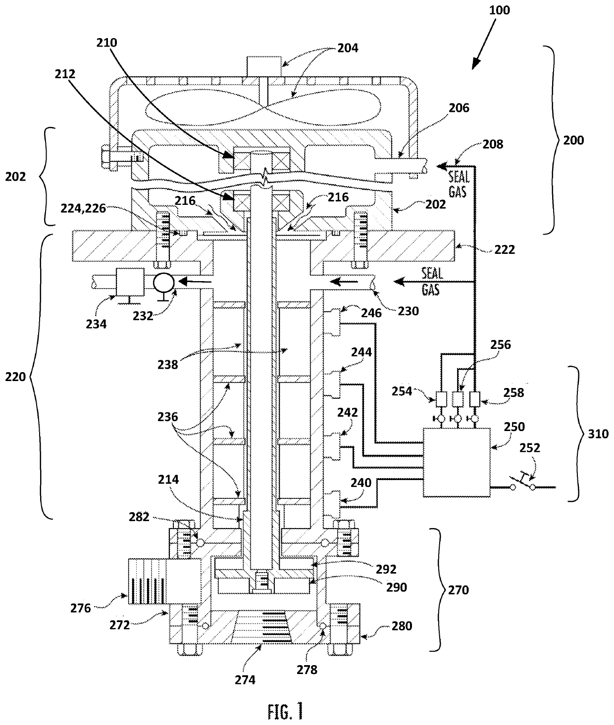
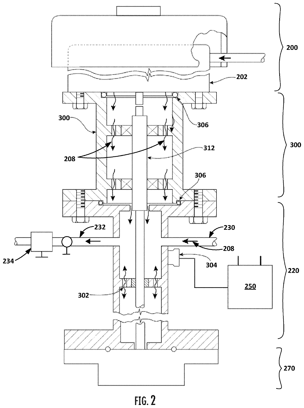
[0016]While this invention is susceptible of embodiment in many different forms, there is shown in the drawings and will herein be described in detail specific embodiments, with the understanding that the present disclosure of such embodiments is to be considered as an example of the principles and not intended to limit the invention to the specific embodiments shown and described. In the description below, like reference numerals are used to describe the same, similar or corresponding parts in the several views of the drawings.

[0017]The terms “a” or “an”, as used herein, are defined as one or more than one. The term “plurality”, as used herein, is defined as two or more than two. The term “another”, as used herein, is defined as at least a second or more. The terms “including” and / or “having”, as used herein, are defined as comprising (i.e., open language). The term “coupled”, as used herein, is defined as connected, although not necessarily directly, and not necessarily mechanical...


PUM


Abstract

The gas seal column pump may comprise a pump drive, a gas seal column, a seal gas control box, and a pump. A drive motor of the pump drive, the gas seal column, and the pump may comprise a hermetically sealed, vertically-oriented, pumping system where the gas seal column is operable to replace mechanical seals around a drive shaft that couples the drive motor to the pump. A pressurized seal gas pumped into the drive motor and the gas seal column may displace corrosive fumes and the product being pumped. A product level may be sensed using a plurality of level sensors. Responsive to inputs from the level sensors, a seal gas control box may regulate the pressure of the seal gas using a plurality of valves. A bearing shaft adapter may be added to provide a special drive shaft of other lengths, diameters, or materials.

Description

COPYRIGHT NOTICE[0001]A portion of the disclosure of this patent document contains material which is subject to copyright protection. The copyright owner has no objection to the facsimile reproduction of the patent document or the patent disclosure, as it appears in the Patent and Trademark Office patent file or records, but otherwise reserves all copyright rights whatsoever.CROSS-REFERENCE TO RELATED APPLICATION[0002]This application claims the benefit of U.S. Provisional Application No. 62 / 973,219 filed Sep. 20, 2019, entitled “Gas Seal Column Pump”.BACKGROUND[0003]In the pumping world dominated by horizontal pumps of all different styles, mechanical seals or shaft packing glands are the most troublesome and highest maintenance cost items over all other pump components.SUMMARY OF THE INVENTION[0004]The answer to eliminating these problems and their associated expenses is to remove both components and reposition the pump components vertically with a gas seal column encasing a drive...

Claims


Application Information

Patent Timeline
IPC IPC(8): F04D29/12F04D13/02F04D29/046F04D29/10
CPCF04D29/122F04D29/102F04D29/046F04D13/021F04D13/08F04D29/108
Inventor KACIN, WILLIAM LOUIS
Owner GSCD CORP
Why Eureka
Try Eureka