Method of Making Applicator With Precision Eye Opening

a technology of eye opening and applicator, which is applied in the field of custom openings of masks, can solve the problems of compromising the actual performance of active agents, ineffective applicators for applying active agents in the eye or lips of many individuals, and difficulty in aligning eye and lip openings, etc., and achieves the effect of reducing eye region bound

Pending Publication Date: 2021-04-08
THE PROCTER & GAMBLE COMPANY
View PDF0 Cites 1 Cited by
  • Summary
  • Abstract
  • Description
  • Claims
  • Application Information

AI Technical Summary

Benefits of technology

[0005]In accordance with embodiments, a method of making a face mask for a face of a human user can include determining a lower eye region bound. For example, the lower eye region bound can be determined by locating a position of one or more of a lowest extent of one or more lower eyelashes of the at least one eye when the eye is open, a lower bound of the eyeball as determined by a peak point of an arc of concavity in the lower eyelid of the at least one eye when the eye is closed, and a lowest extent of one or more upper eyelashes of the at least one eye when the eye is closed. The method can further include determining an upper eye region bound. For example, the upper eye region bound can be determined by locating an upper bound of the eyeball as determined by a peak point of an arc of concavity in an upper eyelid region of the at least one eye when the eye is closed. The eye height is defined by the distance between the lower eye region bound and the upper eye region bound. The method also includes defining the at least one eye opening such that, when the mask is fitted to the face, the first edge is disposed 0 mm to about 10 mm below the lower eye region bound and the second edge is disposed 0 mm to about 10 mm above the upper eye region bound. The method can also include creating the face mask having the at least one eye opening.
[0006]In accordance with embodiments, a method of making a face mask for a face of a human user can include determining a lower eye region bound. For example, the lower eye region bound can be determine by locating a position of one or more of a lowest extent of one or more lower eyelashes of the at least one eye when the eye is open, a lower bound of the eyeball as determined by a peak point of an arc of concavity in the lower eyelid of the at least one eye when the eye is closed, and a lowest extent of one or more upper eyelashes of the at least one eye when the eye is closed. The method can further include determining an upper eye region bound. For example, the upper eye region by can be determined by locating an upper bound of the eyeball as determined by a peak point of an arc of concavity in an upper eyelid region of the at least one eye when the eye is closed. The method can also include setting a firs...

Problems solved by technology

Typical applicators are less than precise with respect to their conformance to the target structure and the use of one-size, or a few sizes, fits all tends to compromise the actual performance of the active agent.
As a result, such applicators are ineffective at applyi...

Method used


Image

  • Method of Making Applicator With Precision Eye Opening
  • Method of Making Applicator With Precision Eye Opening
  • Method of Making Applicator With Precision Eye Opening

Examples


example 1

[0090]An eye opening 102 cutting path was created digital using a method in accordance with the disclosure. FIGS. 7A and 7B illustrate the mask 100 formed from the developed custom eye opening 102.

[0091]Digital data corresponding to a three-dimensional mesh of a face was loaded into Blender graphics program. The mesh of the face was aligned flat, with the nose pointing up in the positive Z direction, the chin and forehead at approximately the same Z height, and the left and right cheeks at approximately the same Z height. The face mesh was oriented to a top down orthographic view. The face mesh was viewed with and without captured texture / color information to provide complementary information on where the reference points are located.

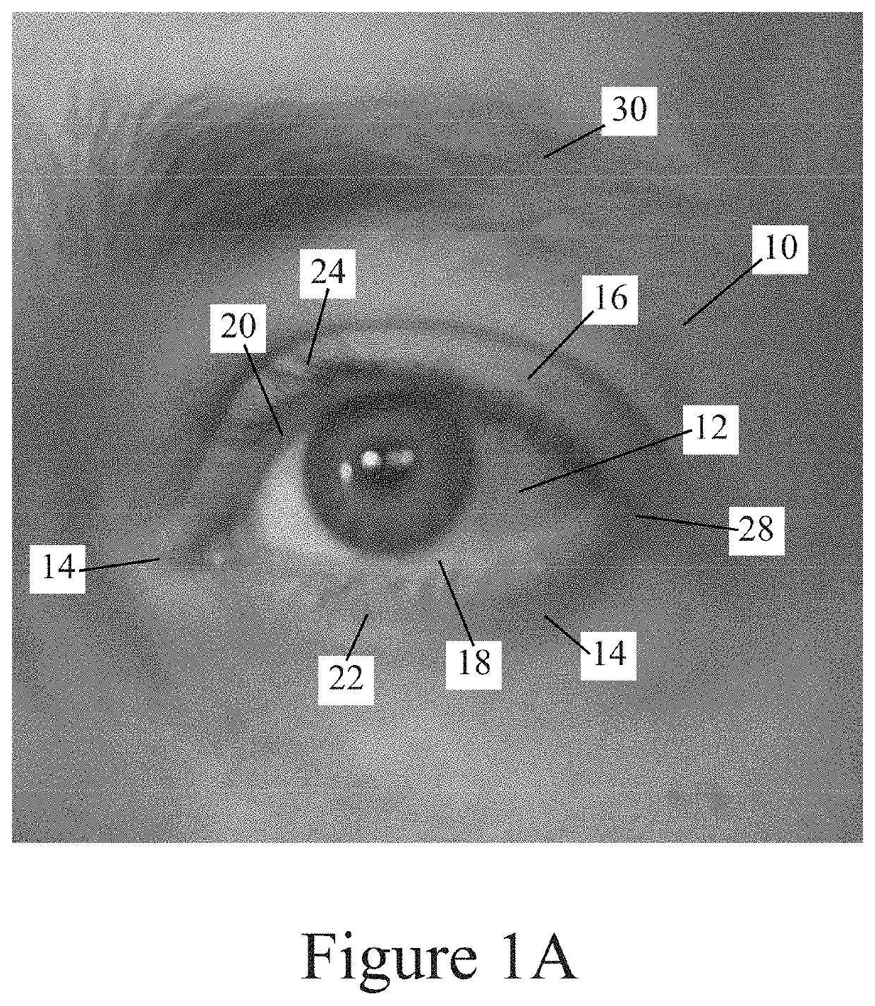
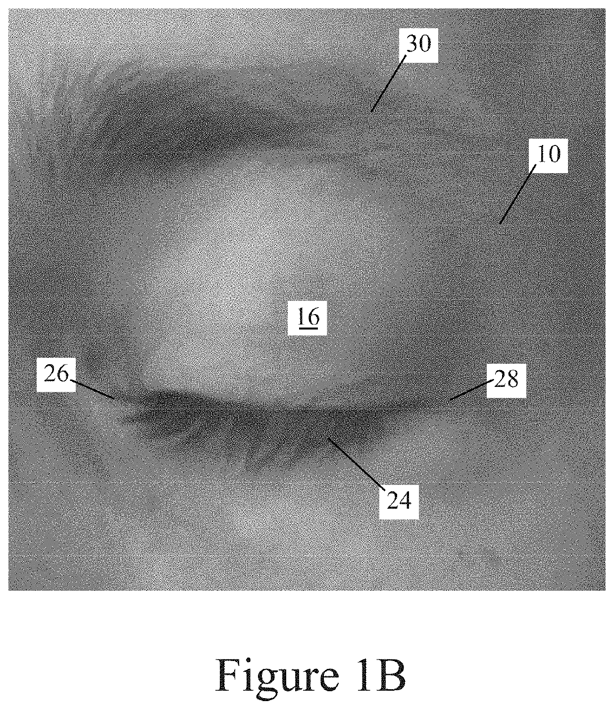
[0092]Four anchor points were selected on the digital geometric representation of the face presented as a mesh. The lower eye region bound 66 was defined at the lowest extent of the upper eyelashes 24 when the eye is closed. A first anchor point 104 was...

example 2

[0095]A face mesh having eye-openings 102 defined therein in accordance with a method of the disclosure was generated for direct printing of the face mask having the eye openings formed upon printing.

[0096]Digital data corresponding to a three-dimensional mesh of a face was loaded into Blender graphics program. The mesh of the face was aligned flat, with the nose pointing up in the positive Z direction, the chin and forehead at approximately the same Z height, and the left and right cheeks at approximately the same Z height. The face mesh was oriented to a top down orthographic view. The face mesh was viewed with and without captured texture / color information to provide complementary information on where the reference points are located.

[0097]Four anchor points were selected on the digital geometric representation of the face presented as a mesh. The lower eye region bound 66 was defined at the lowest extent of the upper eyelashes 24 when the eye is closed. A first anchor point 104 ...

example 3

[0100]A nose opening 114 cutting path was created digitally using a method in accordance with the disclosure. FIG. 12 illustrates the mask 100 formed from the developed custom nose opening 114.

[0101]Digital data corresponding to a three-dimensional mesh of a face was loaded into Blender graphics program. The mesh of the face was aligned flat, with the nose pointing up in the positive Z direction, the chin and forehead at approximately the same Z height, and the left and right cheeks at approximately the same Z height. The face mesh was oriented to a top down orthographic view. The face mesh was viewed with and without captured texture / color information to provide complementary information on where the reference points are located.

[0102]Four anchor points were selected on the digital geometric representation of the face presented as a mesh. Left and right anchor points 120 and 122 are set as the midpoint of the outer nostril walls on either side 46 and 48. Upper anchor point 118 is s...


PUM


Abstract

A method of making a face mask for a face of a human user can include determining a lower eye region bound and determining an upper eye region bound by locating an upper bound of the eyeball as determined by a peak point of an arc of concavity in an upper eyelid of the at least one eye when the eye is closed. The method can also include setting a first anchor point about 0 mm to about 10 mm below the lower eye region bound, and setting a second anchor point about 0 mm to about 10 mm above the upper eye region bound; and defining at least one eye opening for a face mask having first edge that intersects the first anchor point and a second edge that intersects the second anchor point.

Description

FIELD OF THE DISCLOSURE[0001]The disclosure relates to masks having custom openings and methods of creating mask having custom openings defined therein.BACKGROUND OF THE DISCLOSURE[0002]Agents for affecting target structures are well known. Temperature affects may be induced by the application of hot or cold agents to the target. The appearance of a target may be affected by cosmetic and decorative agents. Electric current, voltages, and electric and magnetic fields may be applied to a target using local applicators. For biological targets, surface properties may be impacted by the use of topical application of moisturizers, medicaments and other treatment actives.[0003]The effectiveness of the active agent may be impacted by the nature of the applicator available to facilitate the interaction of the active agent with the target structure. Typical applicators are less than precise with respect to their conformance to the target structure and the use of one-size, or a few sizes, fits...

Claims


Application Information

Patent Timeline
IPC IPC(8): A61M35/00A45D44/00G06T15/10G06V10/764
CPCA61M35/10A45D44/002A61M2207/00A61M2202/0208A61M2210/0612G06T15/10G06V40/171G06V10/764G06F18/24133G06T17/00G06V10/44G06V40/168
Inventor STANLEY, SCOTT KENDYLRAPACH, ANDREW PAULORR, JILL MARLENE
Owner THE PROCTER & GAMBLE COMPANY
Why Eureka
Try Eureka