
Flexible pipe and manufacturing method thereof

Active Publication Date: 2021-04-15
UNION CORP LTD
View PDF0 Cites 0 Cited by
  • Summary
  • Abstract
  • Description
  • Claims
  • Application Information

AI Technical Summary

Benefits of technology

The present invention relates to a flexible pipe and its manufacturing method that can detect leakage caused by damage or breakage of the inner and outer bellows using the variation in amount of oxygen present in the space between the outer bellows and the inner bellows. The flexible pipe is easy to install in equipment while securing its flexibility, and it is possible to accurately inspect the leakage of gas. The process of injecting gas into the space between the outer bellows and the inner bellows required in the related art can be omitted, so that the workability can be improved when manufacturing the flexible pipe. The double bellows can also be prevented from being corrosed by quickly detecting the leakage due to the damage or breakage of the inner bellows.

Problems solved by technology

However, since the bellows is manufactured through a hydroforming process at a high pressure of about 30 to 100 bar, it is difficult to check whether the bellows is doubly formed once a mountain portion is formed, and since the pitting corrosion occurs inside and outside the bellows simultaneously, it is practically impossible to detect whether the corrosion occurs within the double bellows.
In addition, even if it is possible to inject the argon gas within the double bellows, since the bellows is stretched in the longitudinal direction until the pressure applied from the outside and the axial spring force of the bellows are balanced, there is a problem that the product does not maintain the normal shape.

Method used


Image

  • Flexible pipe and manufacturing method thereof
  • Flexible pipe and manufacturing method thereof
  • Flexible pipe and manufacturing method thereof

Examples


Embodiment Construction

[0038]Hereinafter, a flexible pipe and a method of manufacturing the same according to an exemplary embodiment of the present invention will be described in detail with reference to the accompanying drawings.

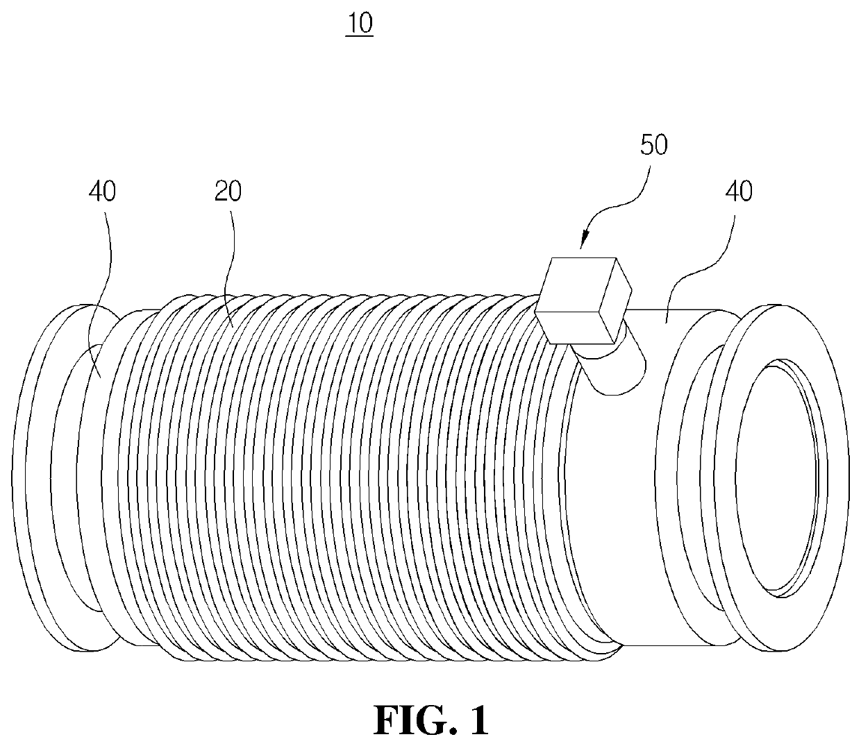
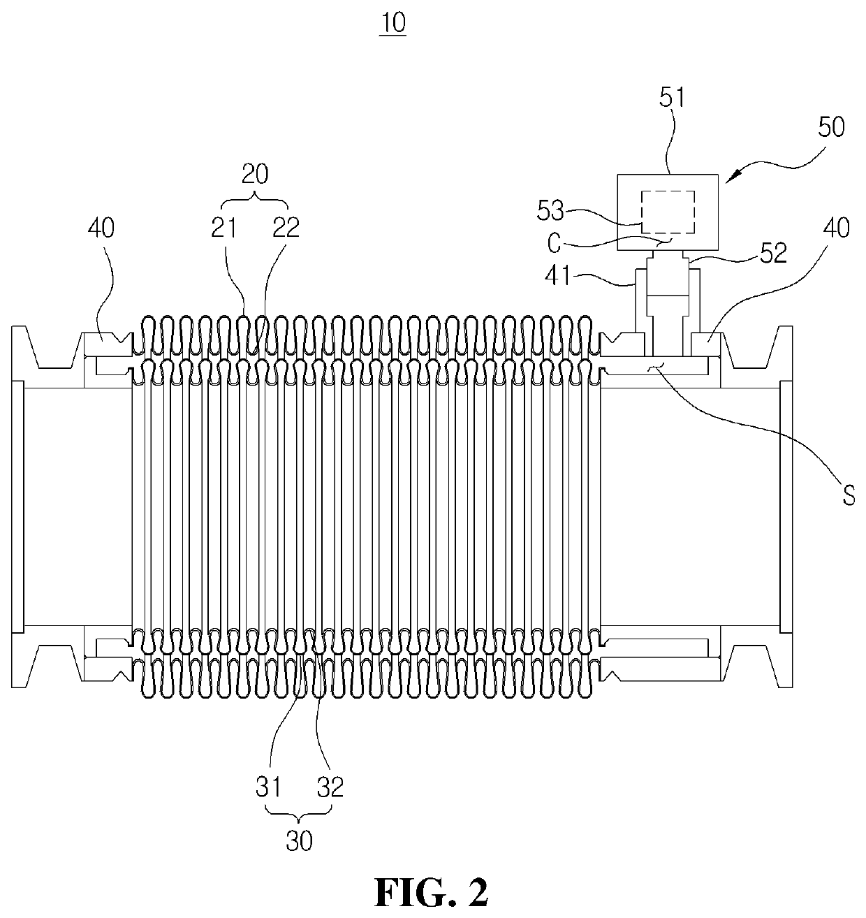
[0039]FIG. 1 is a perspective view of a flexible pipe according to an exemplary embodiment of the present invention, and FIG. 2 is a sectional view of the flexible pipe shown in FIG. 1.

[0040]In the following description, terms indicating directions such as ‘left’, ‘right’, ‘front’, ‘rear’, ‘upward’ and ‘downward’ may be defined based on the state shown in each drawing.

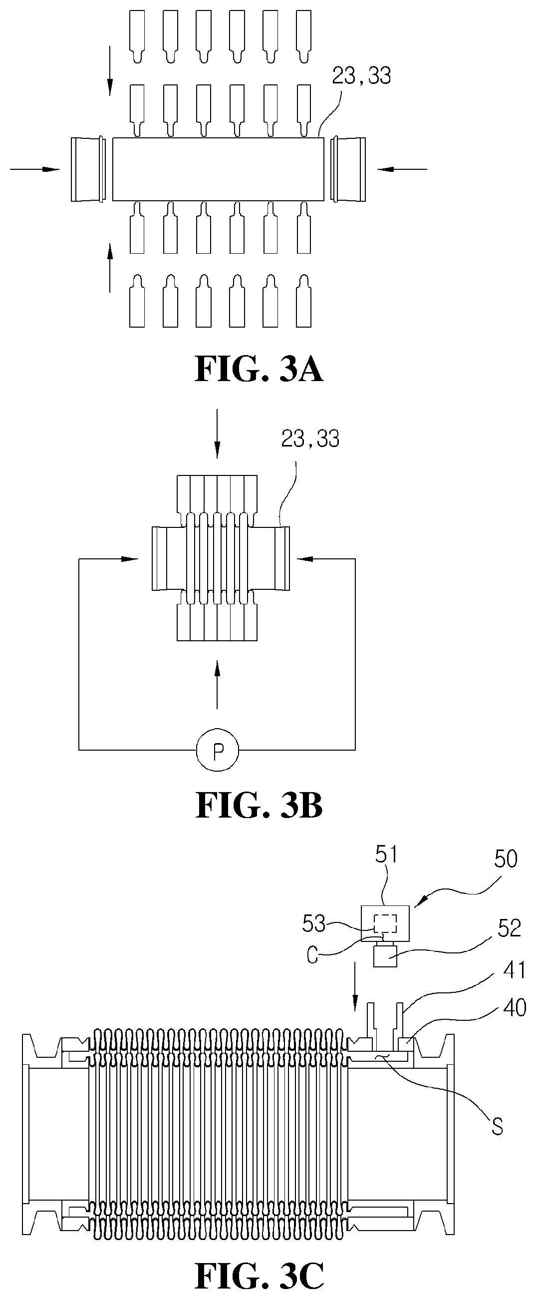
[0041]As shown in FIGS. 1 and 2, a flexible pipe 10 according to an exemplary embodiment of the present invention may include an outer bellows 20 formed in a corrugated tubular shape with mountains 21 and valleys 22, an inner bellows 30 formed in a corrugated tubular shape with mountains 31 and valleys 32 and provided inside the outer bellows 20, a pair of flanges 40 connected to both ends of the outer bellows 20 a...


PUM

PropertyMeasurementUnit
Pressureaaaaaaaaaa

Abstract

Disclosed are a flexible pipe and a manufacturing method thereof. The flexible pipe includes an outer bellows formed in a corrugated tubular shape with mountains and valleys, an inner bellows formed in a corrugated tubular shape with mountains and valleys and provided inside the outer bellows, a pair of flanges connected to both ends of the outer bellows and the inner bellows, respectively, and a detection unit for checking whether leakage occurs due to damage or breakage of the outer and inner bellows by detecting an amount of oxygen present in an air having an atmospheric pressure and filled in an atmospheric space between the outer and inner bellows. Leakage due to damage or breakage of the outer and inner bellows can be detected based on variation in the amount of oxygen present in the space between the outer bellows and the inner bellows.

Description

CROSS-REFERENCE TO RELATED APPLICATION[0001]This application claims priority to and the benefit of Korean Patent Application No. 10-2019-0125407, filed on Oct. 10, 2019, the disclosure of which is incorporated herein by reference in its entirety.BACKGROUND OF THE INVENTION1. Field of the Invention[0002]The present invention relates to a flexible pipe and a method of manufacturing the same, and more particularly, to a flexible pipe used for connecting a vacuum line between components of semiconductor manufacturing equipment and a method of manufacturing the same.2. Description of Related Art[0003]In general, a semiconductor manufacturing process refers to a series of processes that are repeatedly performed on a silicon wafer such as an oxidation process, a diffusion process, a photo process, an etching process, an ion implantation process, a deposition process, and a metal wiring process. Most of the semiconductor manufacturing equipment performing each of these processes is kept in ...

Claims


Application Information

Patent Timeline
IPC IPC(8): F16L27/11F16L51/02G01M3/28
CPCF16L27/11G01M3/2807F16L51/025F16L11/20F16L11/111F16L2201/30G01M3/18G01M3/22F16L11/15F16L57/00F16L55/00H01L21/67017H01L21/67242B29C65/002
Inventor CHO, KYUNG SANG
Owner UNION CORP LTD
Learn More