Rotor assembly for in-machine grinding of shroud member and methods of using the same

a technology of shroud and rotor assembly, which is applied in the direction of machines/engines, engine starters, liquid fuel engines, etc., can solve the problem of lower thermal stability of the second layer and the first layer, and achieve the effect of low thermal stability

Active Publication Date: 2021-04-29
HONEYWELL INT INC
View PDF0 Cites 1 Cited by
  • Summary
  • Abstract
  • Description
  • Claims
  • Application Information

AI Technical Summary

Benefits of technology

[0007]In one embodiment, a turbomachine is disclosed that includes a shroud and a rotor rotatably supported within the shroud. The rotor includes a first blade and a second blade. The first blade has a first blade tip oriented toward the shroud, and the second blade has a second blade tip oriented toward the shroud. The first blade tip and the second blade tip respectively include a base and a first layer layered over the base and disposed outward radially therefrom. The second blade tip includes an abrasive second layer layered over the first layer of the second blade tip such that the first layer of the second blade tip is disposed radially between the base and the abrasive second layer of the second blade tip. The first layer of the first blade tip and the first layer of the second blade tip have a material hardness that is lower than that of the shroud. The abrasive second layer has a lower thermal stability than the shroud and the first layer of the second blade tip. The rotor is configured to rotate within the shroud in a grind operation and, subsequently, in a post-grind operation. The abrasive second layer of the second blade tip, in the grind operation, is configured to contact and remove material from the shroud, and to wear away from the second blade tip, thereby revealing the first layer of the second blade tip for the post-grind operation. The first layer of the first blade tip is spaced apart with at least some radial clearance from the shroud in the grind operation and in the post-grind operation.

Problems solved by technology

Also, the abrasive second layer has a lower thermal stability than the shroud and the first layer.

Method used


Image

  • Rotor assembly for in-machine grinding of shroud member and methods of using the same
  • Rotor assembly for in-machine grinding of shroud member and methods of using the same
  • Rotor assembly for in-machine grinding of shroud member and methods of using the same

Examples


Embodiment Construction

[0022]The following detailed description is merely exemplary in nature and is not intended to limit the present disclosure or the application and uses of the present disclosure. Furthermore, there is no intention to be bound by any theory presented in the preceding background or the following detailed description.

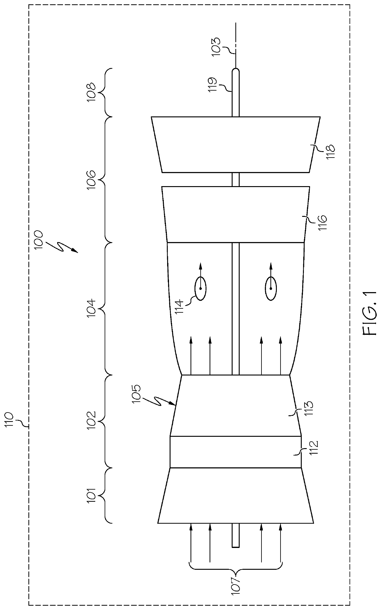
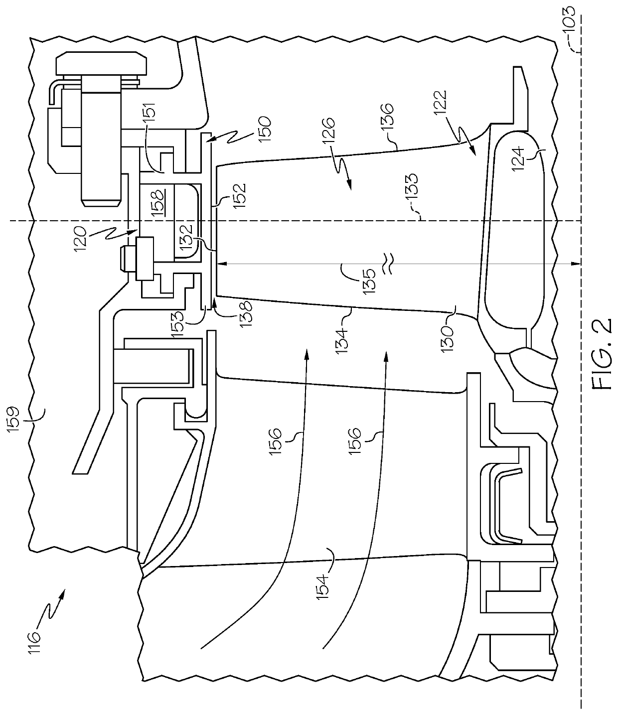
[0023]The present disclosure provides a turbomachine, such as a turbine section of a gas turbine engine with improvements directed to the blade tips of the rotor in combination with a shroud that may be shaped thereby. These improvements allow the rotor to perform an in-machine (in-engine) grind operation in the initial uses of the turbomachine. As such, the shroud surface may be tailored to a shape and dimension corresponding to at least some of the blade tips.

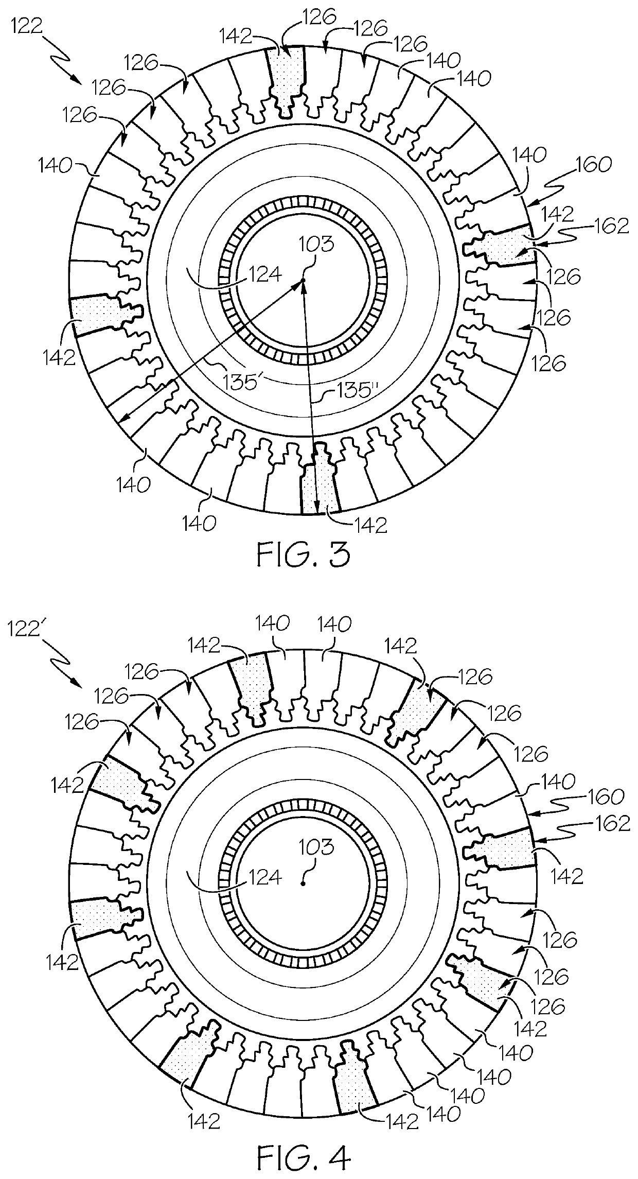
[0024]More specifically, the rotor assembly may include a plurality of blades, including one or more first blades and one or more second blades. The blade tips of the first and second blades may include different mat...


PUM

PropertyMeasurementUnit
thicknessaaaaaaaaaa
thicknessaaaaaaaaaa
thicknessaaaaaaaaaa

Abstract

A turbomachine includes a shroud and a rotor, which includes first and second blades. A first blade tip and a second blade tip respectively include a base and a first layer. The second blade tip also includes an abrasive second layer layered over the respective first layer. The first layer has a lower material hardness than the shroud. The second layer has a lower thermal stability than the shroud and the first layer. The rotor performs a grind operation and, subsequently, a post-grind operation. The second layer, in the grind operation, contacts and removes material from the shroud, and wears away, thereby revealing the first layer of the second blade tip for the post-grind operation. The first layer of the first blade tip is spaced apart with at least some radial clearance from the shroud in the grind and post-grind operations.

Description

STATEMENT REGARDING FEDERALLY SPONSORED RESEARCH OR DEVELOPMENT[0001]This invention was made with Government support under DTFAWA-15-A-80017 awarded by the FEDERAL AVIATION ADMINISTRATION (FAA) CONTINUOUS LOWER ENERGY, EMISSIONS AND NOISE II (CLEEN II) TECHNOLOGIES DEVELOPMENT PROGRAM. The Government has certain rights in the invention.TECHNICAL FIELD[0002]The following relates to a rotor assembly of a turbomachine, such as a gas turbine engine, and more particularly relates to a rotor assembly for in-engine grinding of a shroud member and methods of using the same.BACKGROUND[0003]Turbomachines, such as gas turbine engines are often used in aircraft and other applications. For example, gas turbine engines used as aircraft main engines may provide propulsion for the aircraft but are also used to provide power generation. It is desirable for such systems to deliver high performance in a compact, lightweight configuration.[0004]A rotor of a turbomachine can rotate within a stator, and ...

Claims


Application Information

Patent Timeline
Patent Type & Authority Applications(United States)
IPC IPC(8): F01D5/28
CPCF01D5/288F05D2240/30F05D2300/17F05D2300/611F05D2300/133F05D2300/506F05D2300/2282F01D11/122F01D5/20F01D19/00F04D29/526F05D2240/307F05D2230/90F05D2260/85F05D2300/609F05D2300/502F05D2300/175Y02T50/60
Inventor MITTENDORF, DONALDAMATO, KRISTACONKLIN, NICOLELUDWIG, BRENTMORRIS, MARKSTANLEY, RYONTILMAN, DONALDYUN, HEEMANN
Owner HONEYWELL INT INC
Why Eureka
Try Eureka