
Stator assembly comprising electrical insulation devices having an outer surface with elevated surface portions

Pending Publication Date: 2021-04-29
SIEMENS GAMESA RENEWABLE ENERGY AS
View PDF2 Cites 0 Cited by
  • Summary
  • Abstract
  • Description
  • Claims
  • Application Information

AI Technical Summary

Benefits of technology

The patent describes a stator assembly that reduces unwanted current flow (creepage) between the conductive parts of the end winding and the frame structure, which improves the performance and efficiency of an electromechanical transducer. This is achieved by adding elevated surface portions to the outer insulation portion of the outer insulation. The provided stator assembly helps to increase the electric resistance to creepage currents and reduce the amperage of such currents, resulting in a compact, economical, and efficient electromechanical transducer.

Problems solved by technology

Hence, with higher voltage class of the electromechanical transducer, it is necessary to increase creepage distance leading to an increase of the length of the end winding portion, which in turn will increase the resistive loss in the electromechanical transducer and reduce the performance of the electromechanical transducer.
However, also such an extension increases the length of the end winding portion because (i) the end winding portion is bended and (ii) the insulation device needs to end before the bending of the end winding starts.
Hence, an elongation of insulation device goes along with an increased length of the end winding portion which, as described above, reduces the performance of the electromechanical transducer.
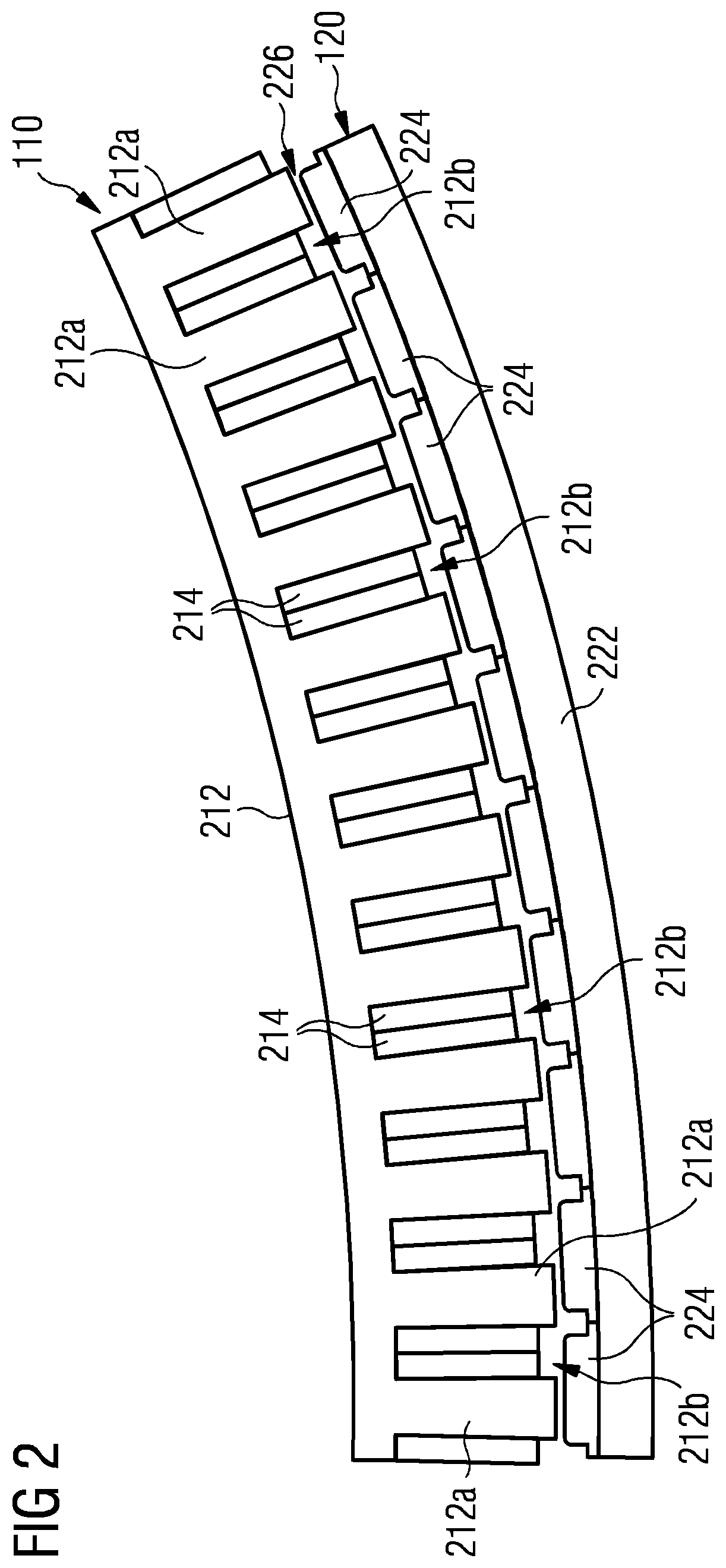
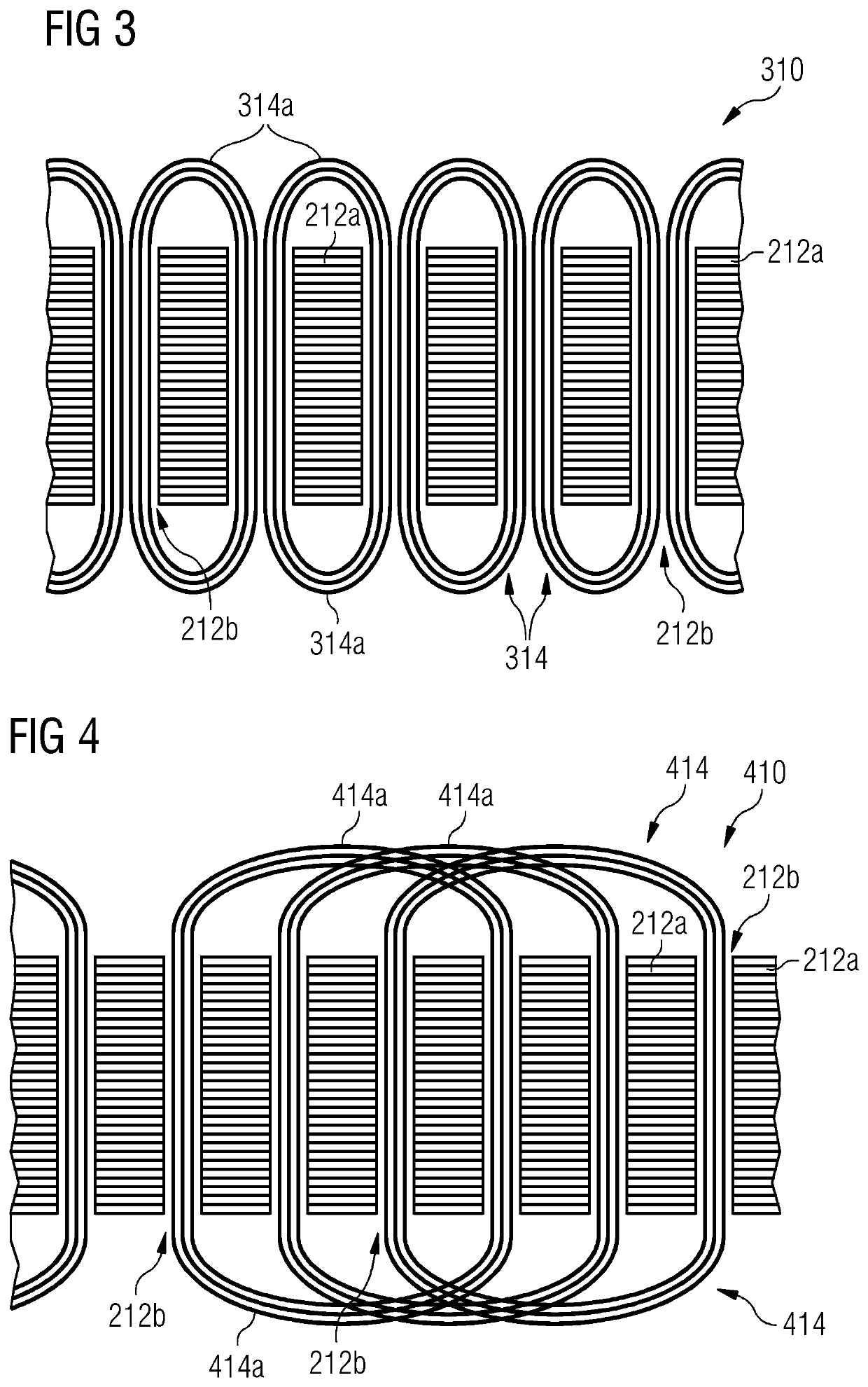
In this case the presence of elevated (and of course also non elevated) surface portions may mean that there is a non-uniform thickness of the insulation material of the outer insulation portion surrounding the conductor material of the respective end winding.

Method used


Image

  • Stator assembly comprising electrical insulation devices having an outer surface with elevated surface portions
  • Stator assembly comprising electrical insulation devices having an outer surface with elevated surface portions
  • Stator assembly comprising electrical insulation devices having an outer surface with elevated surface portions

Examples


Embodiment Construction

[0050]The illustration in the drawing is schematic. It is noted that in different figures, similar or identical elements or features are provided with the same reference signs or with reference signs, which are different from the corresponding reference signs only within the first digit. In order to avoid unnecessary repetitions elements or features which have already been elucidated with respect to a previously described embodiment are not elucidated again at a later position of the description.

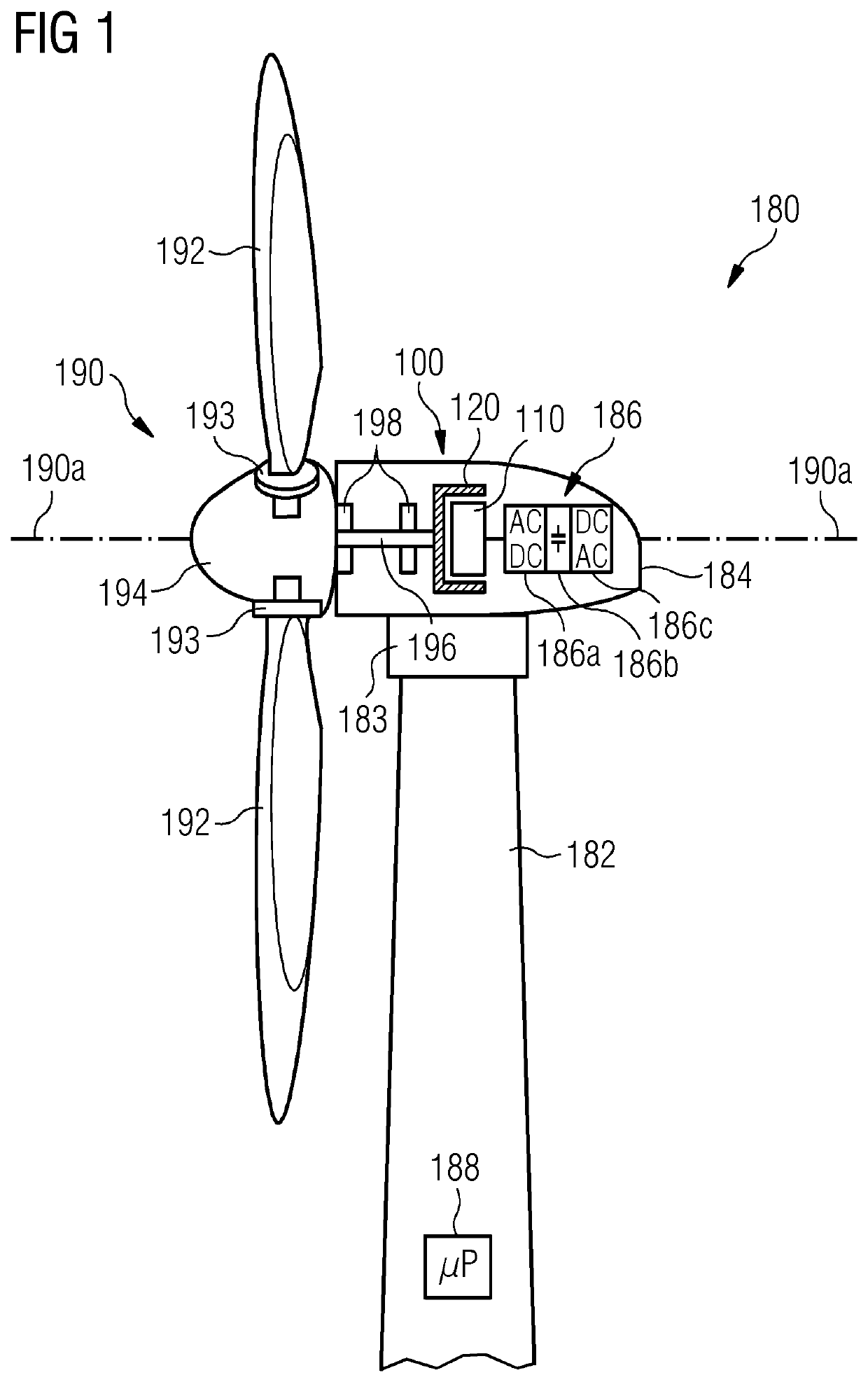
[0051]FIG. 1 shows a wind turbine 180 according to an embodiment of the present invention. The wind turbine 180 comprises a tower 182, which is mounted on a non-depicted fundament. On top of the tower 182 there is arranged a nacelle 184. In between the tower 182 and the nacelle 184 there is provided a yaw angle adjustment device 183, which is capable of rotating the nacelle 184 around a not depicted vertical axis, which is aligned with the longitudinal extension of the tower 182.

[0052]The wi...


PUM


Abstract

A stator assembly including a frame structure having a stator teeth being circumferentially distributed around a longitudinal axis, wherein in between respective two neighboring stator teeth there is formed one stator slot; a winding system having a plurality of electric windings, wherein respectively one electric winding is wound around at least one stator tooth and is partially accommodated within two stator slots and each electric winding comprises an end winding portion which axially protrudes from the frame structure; and an insulation arrangement having a plurality of electric insulation devices, each insulation device surrounding a part of one electric winding is provided. Each insulation device includes an inner insulation portion being accommodated within the respective stator slot and an outer insulation portion protruding from the frame structure and surrounding a part of the respective end winding portion. The outer insulation portion includes an outer surface which includes elevated surface portions.

Description

CROSS-REFERENCE TO RELATED APPLICATIONS[0001]This application claims priority to European Patent Application No. 19205613.3, having a filing date of Oct. 28, 2019, the entire contents of which are hereby incorporated by reference.FIELD OF TECHNOLOGY[0002]The following relates to the technical field of electromechanical transducers such as electric motors or electric generators. Such electric generators can be employed e.g. in wind turbines for converting the mechanical power provided by wind into electric power to be fed e.g. into a utility grid. Specifically, the present invention relates to electric insulation measures within a stator assembly for an electromechanical transducer.BACKGROUND[0003]An electromechanical transducer, such as an electric generator installed in a wind turbine, comprises a rotor assembly which rotates relative to a stator assembly. The stator assembly includes a frame structure having a plurality of stator teeth being circumferentially distributed around a ...

Claims


Application Information

Patent Timeline
IPC IPC(8): H02K3/48H02K3/34H02K3/12H02K3/28H02K3/02H02K1/16H02K7/18F03D9/25
CPCH02K3/48H02K3/345H02K3/12F03D9/25H02K3/02H02K1/165H02K7/1838H02K3/28H02K1/146H02K3/38H02K3/50H02K1/2786H02K16/02F03D80/00H02K3/40Y02E10/72
Inventor GROENDAHL, ERIKSAMANTA, SUBHRATHOMAS, ARWYN
Owner SIEMENS GAMESA RENEWABLE ENERGY AS
Learn More